2 - motors running through contacts won't start up

Status
Not open for further replies.
Maybe I'm lost here but the circuits seem to trace
out to an operable system. This almost ( to me )
is a problem where the output from the 2 speed
setup is connected within the motor. I admit I may
not seen any errors in the wiring diagram and the
switch is indicated as a three position switch and
there are no crossovers ( once again as I see it )
With these kind of problems, it may be a good idea
to start at the motors, check them and move upstream
in a systematic way. This has saved me countless hours
and is a process of elimination.

This kind of situation is definately strange, but start at the
simple end (motors) first. I did not study the diagram in
great detail, but I don't think that's the problem ( could be
but I just don't see it )

JR
 
unhook the motors and check voltage at the side of the the contactors that the motor leads hook to.

operate the switches in all positions

Do you have the correct voltage there?
 
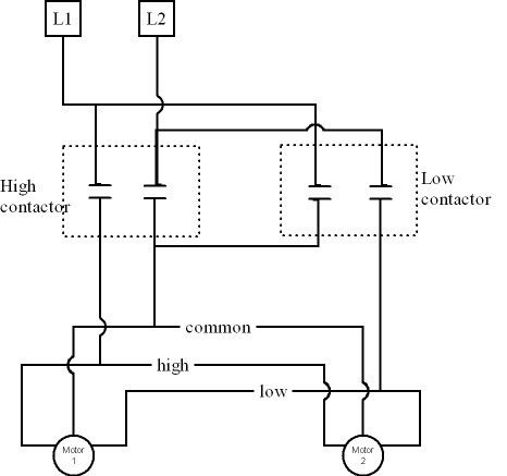
Contactors don't make any noise at anytime only when opened or closed. All noise comes from motor. I didn't manually hold in or close contacts, I just spliced through and controlled by breaker and they fired up no problem. Funny thing is I just wired 2 bigger fan motors almost exactly the same in same building and no issue at all with them starting at same time. I know everything leads to my control wiring... I sketched a quick diagram it is attached. Thanks for everyone s effort!!
If your drawing shows what you do actually have for connections, then when you select the "Hi" contactor with the switch it closes it's contacts sends L1 to the high speed lead on both motors, but only motor 1 will run because the common lead comes back to L2 on the high contactor, but common on motor 2 comes back to the low contactor that still has open contacts - but you do have the two low speed leads connected together and probably some circulating current between the two motors resulting in improper voltage across both high and low speed coils in both motors - that is why it just makes noise, you need to somehow supply each motor in a manner that only applies voltage to only one speed tap and the common lead. (you need to close the "common" to both motors no matter which speed is being selected as a place to begin with) You can either do this with two contactors large enough to handle both motors at same time or with four contactors (hi and lo for each motoor). Mechanical interlock between Hi and Lo contactors is not a bad idea either even though that is not contributing to your current problem.
 
I didn't draw in the control circuit but wire the power circuit like this


or use 4 contactors if you feel you need a individual contactor for each speed for each motor but you will have two contactors wired to hi control lead and two wired to low control lead. This may be necessary if you need motor overloads incorporated as well, but I'm guessing the motors probably have internal overload protection already.
 
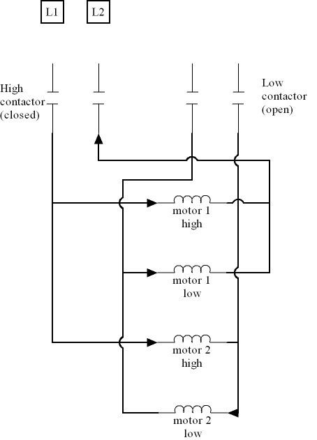
Here is what you likely have going on - again control circuit omitted just power wiring shown:


When High contactor is closed you put full voltage across motor 1 high winding, but also put motor 2 high winding (from here L2 contact on low contactor is open so the circuit proceeds to:), motor 2 low winding and(back to) motor 1 low winding all in series across full voltage. If those three windings were all same impedance you would have 1/3 voltage across each of them, but the low and high windings will be different impedance so voltages across each of those three is not equal.

Edit: I see I forgot to draw in the line side of contactors - but I think you know what is there.
 
J.P.'s comment and kwired's initial diagram are both
good ways to solve this. Test the voltage without
the motor and the first diagram (kwired) are both
systematic ways of solving problems like these.
Try to check voltage as connected now (J.P.) and
if that checks out go to a different wiring method.
I recall the starter of this thread saying that there
was another setup like this that worked. And this one
worked with the controls involved. If possible, can
the functioning wiring installation have a picture or
hand drawn diagram to compare? There are good
suggestions above this post, and if it's not too late
look into them. I've done many automatic control
systems that I came up with myself and for me,
it is hard to find fault with others when a quick
overview doesn't throw up any major flags.
Sometimes the most simple error or oversight
can get these situations.

As always I hope a solution will present itself.

JR
 
I didn't draw in the control circuit but wire the power circuit like this


or use 4 contactors if you feel you need a individual contactor for each speed for each motor but you will have two contactors wired to hi control lead and two wired to low control lead. This may be necessary if you need motor overloads incorporated as well, but I'm guessing the motors probably have internal overload protection already.


You have the common off L2 so shouldn't your Low go to L1 like your high does just a question?
 
PackerBacker

This is the circuit you drew you might have had one common a little different.
I'm just not really sure how you wanted the fans to run when you first energize them?

2%20Fan%20Motor%20control_zpshi7obfe5.jpg


Have a great night:Ronald :)
 
You have the common off L2 so shouldn't your Low go to L1 like your high does just a question?
That was not intentional should have looked it over better before submitting it:slaphead:

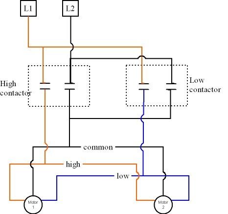
corrected it and colored some of the conductors to help make it easier to tell them apart.
 
PackerBacker

This is the circuit you drew you might have had one common a little different.
I'm just not really sure how you wanted the fans to run when you first energize them?

2%20Fan%20Motor%20control_zpshi7obfe5.jpg


Have a great night:Ronald :)
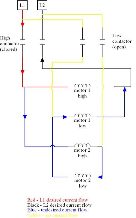
That is how I interpreted his hand written drawing, except your change to the switch in control circuit, I figured he had a SPST switch with a center off position - but that wouldn't have any impact on the troubles he is having. Problem as I mentioned and tried to point out the current paths in post 46 is we are sending L1 to both motors either via High lead or Low lead, but only connecting one or the other motor Common lead - this puts one winding of one motor in series with both windings of the other motor - exactly which ones depends which contactor is engaged.

That leaves us with one motor with full voltage across one speed winding, and partial voltage across the other speed winding - they will work against one another and you may or may not get any torque out of the motor, but likely do get a lot of noise out of it. The other motor only has partial voltage across both windings - probably has little to no torque at all, but because of the reduced voltage is likely not nearly as noisy as the other motor.

Bottom line is no matter how the lines are switched - L2 needs to pass through to both common leads no matter which speed is selected.


I agree, I wasn't sure if he wanted both motors to be the same speed, I just assumed he did.
If he wires it like this he want have any problems I don't think. His drawing indicates he has the skill to do this.
But he just need to make sure it is wired up right.

Have a great night:Ronald :)
 
My Bad again

My Bad again

I agree, I wasn't sure if he wanted both motors to be the same speed, I just assumed he did.
If he wires it like this he want have any problems I don't think. His drawing indicates he has the skill to do this.
But he just need to make sure it is wired up right.

Have a great night:Ronald :)

Oops did I leave a jumper off? Only one contactor energizes at a time.

So we need a jumper between the two commons on the load side of the contactors.

And now I'm a little concerned about what Tom said about the interaction between Hi and Low speed leads.
The way I traced the current flow I think they will nullify,but I'm not smart enough to stake my life on it.
I would just have to find out with trial and error just like the OP is.


Ronald :)
Follow the arrows in the drawing I posted in post 46 (I probably could have done a better job on that drawing but I think it is clear enough if you start with L1 follow current path assuming the left contactor is closed and the right one is open)- there will be current in both speed windings in both motors - if L2 is only connected to one of the motor common leads, but as I have tried to explain twice now there will only be full voltage across one speed winding (out of all four windings involved with both motors) but the other three windings will be in series with each other so they all see partial voltage. This current flowing in places it shouldn't be all at the same time will result in motor having two torque values trying to be applied at same time and they will counter each other, and probably burn motor out if left that way for too long.
 
Follow the arrows in the drawing I posted in post 46 (I probably could have done a better job on that drawing but I think it is clear enough if you start with L1 follow current path assuming the left contactor is closed and the right one is open)- there will be current in both speed windings in both motors - if L2 is only connected to one of the motor common leads, but as I have tried to explain twice now there will only be full voltage across one speed winding (out of all four windings involved with both motors) but the other three windings will be in series with each other so they all see partial voltage. This current flowing in places it shouldn't be all at the same time will result in motor having two torque values trying to be applied at same time and they will counter each other, and probably burn motor out if left that way for too long.
I fixed it so it is hopefully easier to follow what is happening there.
 
I fixed it so it is hopefully easier to follow what is happening there.


Well I guess that means each contactor needs a Normally closed contact
to open the opposite speed lead then.

I did take a little more time and retraced your diagram its fine.

Ronald :)
 
I am bothered with the Low & Hi speeds being common with each other. I would be inclined to make sure the Hi of M1 & M2 are separated unless they are to be energized. Same with Lo. I lack the education to explain precisely but each of those windings will have some voltage on it and that may be messing with the magnetic fields in each motor.
Just so happened there was a two speed pump motor on the workbench this morning and someone put power to the hi and low windings instead of to the common and one of the speeds..... wasn't me I swear....cough, cough, ahhhemmm, someone who should wear his reading glasses.....

I don't have the typing skills to explain why that was bad either, but it rattled the pipes loud enough that folks came out of the office.
 
Well I guess that means each contactor needs a Normally closed contact
to open the opposite speed lead then.

I did take a little more time and retraced your diagram its fine.

Ronald :)
least cost solution is to do it the way I did in the drawing in post 50 - make sure the L2 gets sent to both motors no matter which contactor is engaged, or even not running L2 through the contactor - as a controller that is still acceptable, it is motor disconnecting means that must open all ungrounded conductors.

Otherwise the next simpler method might be a high and low contactor for each motor. The problem here is power backfeeding through the unused winding of the non selected speed in one motor and through the other motor (wouldn't happen if each motor had individual contactors or if the second motor actually had L2 present at the common lead) and then eventually finding a way to L2.

Omit connecting L2 when you have individual contactors just leaves the motor on an open circuit and nothing happens - which may give you better results down the road if something fails, if the L2 contact on one of the contactors fails down the road - you get exactly the same problem the OP has now.
 
Status
Not open for further replies.
Top