winnie
Senior Member
- Location
- Springfield, MA, USA
- Occupation
- Electric motor research
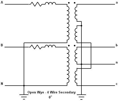
In a wye system, V N to A must be 120 degrees away fro V N to B. However V A to B must be 60 degrees away from V A to C.
The latter is also true for a delta system. V A to B must be 60 degrees away from V A to C.
I believe that as you have drawn things, V A to B is 60 degrees away from V C to A, which is the same thing as saying that V A to B is 120 degrees away from V A to C.
I must admit, however, that it took me a whole day of pondering on this one, and I'm still a bit confused.
In any case, I believe that the open wye to open delta approach would be a good one for the OP; and if the diagram is wrong things could be fixed by swapping the connection on one transformer. Just check the voltages before you connect anything.
-Jon
 Oh, who cares...with a neutral reference: Va=120<0, Vb=120<180, Va-Vb = 120<0 - 120<180 = 240<0