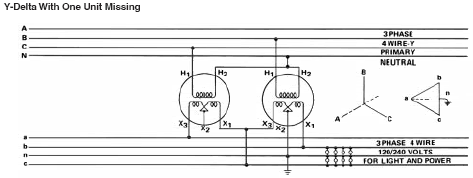
2 phases of 3 phase service to 3 phase.

Status
Not open for further replies.
I have a 240/120 3 phase 4 wire service,
The phase to phase is 240, the phase to ground of my service is 120/120/and about 200. (the high leg). I am have at the service pole behind my transmitter building only two transformers. A 15 KVA and a 37.5 KVA.
The are only two primary high voltage wires feeding these two transformers.
These high voltage wires come from a main service line about 750 feet
from from my building. This main feed has three phases. The power company only brings two of these three phases on to my property. They obtain my three phase service described above from two primary phases and a nuetral. My questions is can anyone supply or direct me to a connection drawing of for this service, with the drawing having the phase notation and an explaination of the generation of the third phase. I think I know how this works, but I want to confirm. I also would like to know the effective KVA of this service. My goal is to change the service to a three transformer, closed Delta service, fed by all three primary phases.
John,

You have an open wye to open delta connection.

There is no direct method to tell you the equivalent three phase transformer capacity that you have.

Open delta 4-wire transformer banks are sized based on the 3-phase load plus the single phase load. So, assuming that typical procedures were followed, you have an open-delta 15kVA transformer for 3-phase 240V loads and 22.5kVA for single phase 120/240V loads.

The closed delta equivalent rating of an an open delta transformer bank are:
For equally sized units (no center tap)
Three Phase KVA Capacity = Total KVA of both units X .86 = KVA of single unit X 1.73

For unequally sized units, a commonly used formula is:
KVA(a) = .58T
KVA(center tap) = .58T + S
where T= three phase load and S = single phase load

For single core three phase units you can use:
KVA = T + 2.5 X (120V loads)

So in your case, you probably have the ability for 25KVA balanced three phase + 22KVA single phase. If I was replacing this with a single closed delta center tapped unit I would use one rated at least 53KVA 240/120 3PH 4W.
 
One question. Say each transformers have a power rate of 1 p.u. The maximum power output that you can get from this two (as the picture shows) transformers together will be 2 p.u??

The equivalent is 1.73 p.u.
Assuming balanced three phase loading.
 
My questions is can anyone supply or direct me to a connection drawing of for this service, with the drawing having the phase notation and
an explaination of the generation of the third phase.
I can describe it. It helps if you go outside and look at the transformers' load bushings, which should be on the side of the cans. Start with the larger transformer: There should be three conductors attached to it, with the center one (or sometimes two, jumpered together) bonded to the can, and connected to the neutral.

It is exactly, and I mean exactly, the same as your typical 120/240v service, with 240 L-L and 120 L-N. Let's call the lines phase A and phase B for now. Then, they add a second transformer, with no (or an unconnected) center terminal(s), which is also 240v L-L. One end of this connects to, let's say, phase A.

Let's call the other end of the new transformer phase C. Obviously, there is 240v between phases A and B, and between A and C. But, what about between B and C? There is also 240 between B and C because, if you had a full Delta, and opened the lines at any corner, there would theoretically be zero volts across the gap.

Likewise, if you removed one transformer, there would still be 240v between where the terminals were connected. The primary timing keeps that stable. In reality, they usually call the two 120-to-N lines phases A and C, and the high leg (which is only because we choose to ground the center tap) phase B.

Added: By the way, you can use the 120/240v 1ph section as you would any similar supply including grounding/bonding, and the 240v 3ph section just as you would any other, including 240v 1ph. But, if the load requires the neutral, you can only use the two 120v lines. Avoid the high-leg-to-neutral connection.
 
Last edited:
Thanks,

Thanks,

Jim, the comments you and Larry Fine made are very helpful and
greatly appreciated. When and if I can upload diagrams and photos
I will. You are both describing what I have.
We can if your patience allows get to the core of my question.
How is the 120 degree per leg phase rotation achived from two
phases, using two transformers?
Thanks,

JohnRoss
As a simple explanation:

Because you have defined three points relative to each other. Draw a triangle. Erase one line. Draw it back. The relationship between the two untouched lines constrains the location of the third line.

The two untouched lines are the two transformers you have. They define the relationship between the endpoints where the third line (transformer) will fit.

The voltage vectors along the two untouched transformers are rotating in a relative relationship to each other. As they rotate, the open endpoints also rotate. The voltage vector between these open endpoints is the same voltage vector you will get if you stick a transformer between these endpoints.
 
...
How is the 120 degree per leg phase rotation achived from two
phases, using two transformers?
Y-Delta2pot.gif


In the above diagram, let V_AN (read: voltage at A referenced to N) be our 0? reference for the system. The following then applies to the left and right pots, respectively:
V_H1-H2=V_CN@–240? thus V_X1-X3=V_ca@–240?
V_H1-H2=V_BN@–120 thus V_X1-X3=V_bc@–120?​
Being the magnitudes of V_ca@–240? and V_bc@–120? are equal, the open-terminal to open-terminal voltage will be identical in magnitude due to the inside angle measuring 60? when referenced to "c" terminal and measure V_ab@0?.

Note the included phase diagram confirms the above.
 
Last edited:
Status
Not open for further replies.
Top