Clodbuster
Member
- Location
- Eastern Washington
Hi everyone,
First post on the site but I've lurked for a long time and learned from you all. Thanks for that and take it easy on the new guy for his first question all right?!
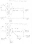
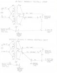
So what I've got is a transformer installation that I don't believe is grounded correctly. The work electrician installed a new Acme General Purpose Transformer, No. T 2-53013-4S, 3 kVA. Windings are 240x480 Primary and 120/240 Secondary. It's purpose is to step down 240V single phase power to 120V to allow installation of a convenience GFCI receptacle at some distance (1175 ft) from the nearest panel. I sized the conductors for voltage drop and selected the transformer and the electrician installed it. When I checked it out I found weird voltages from line-ground (22V) and neutral-ground (40V) on the receptacle, but the line-neutral checks out at 120V. I think the grounding is incorrect as the receptacle ground (EGC) on the secondary side is shared with the EGC on the primary side. Also, there is no neutral-ground bond on the secondary side.
I've been looking at the code requirements and I talked to the electrician to see how he wired it. I think I have figured out how to fix but want to check myself before taking this to the electrician to get my ducks in a row so to speak. Here's some wiring diagrams of how it was done and how my interpretation of the code says it needs to be done. If anyone has any disagreements or suggestions I would appreciate hearing them.
I'm in WA state and familiar with NEC 2008.
Thanks.
First post on the site but I've lurked for a long time and learned from you all. Thanks for that and take it easy on the new guy for his first question all right?!
So what I've got is a transformer installation that I don't believe is grounded correctly. The work electrician installed a new Acme General Purpose Transformer, No. T 2-53013-4S, 3 kVA. Windings are 240x480 Primary and 120/240 Secondary. It's purpose is to step down 240V single phase power to 120V to allow installation of a convenience GFCI receptacle at some distance (1175 ft) from the nearest panel. I sized the conductors for voltage drop and selected the transformer and the electrician installed it. When I checked it out I found weird voltages from line-ground (22V) and neutral-ground (40V) on the receptacle, but the line-neutral checks out at 120V. I think the grounding is incorrect as the receptacle ground (EGC) on the secondary side is shared with the EGC on the primary side. Also, there is no neutral-ground bond on the secondary side.
I've been looking at the code requirements and I talked to the electrician to see how he wired it. I think I have figured out how to fix but want to check myself before taking this to the electrician to get my ducks in a row so to speak. Here's some wiring diagrams of how it was done and how my interpretation of the code says it needs to be done. If anyone has any disagreements or suggestions I would appreciate hearing them.
I'm in WA state and familiar with NEC 2008.
Thanks.
")