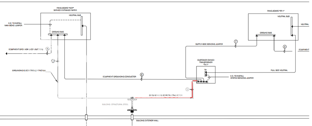
I designed a grounding/bonding diagram for a service-entrance rated 480V panel feeding a 480V/208Y/120V transformer, which in turn fed a 208V panel. Please see partial screenshot of the diagram in photobucket link below which shows the configuration. Please note the “building structural steel” shown on the diagram is not the same physical column, but representative of structural steel, which was exposed and accessible in the building.
250.30(A)(4) Grounding Electrode; 250.30(A)(5), Grounding Electrode Conductor, Single Separately Derived System, & 250.104(D)(2), Structural Metal
A question was posed by the electrical project manager: Why is a separate GEC connection needed at TX-1 (highlighted in red on diagram)? His point was that the EGC from MDP feeding TX-1 ultimately provides a connection back to the building's GES and the GEC connection at the TX-1 to structural steel appeared redundant.
The response I provided was that while I agreed that his point was electrically valid, it appeared that a reading of 250.30(A)(4), 250.30(A)(5), and 250.104(D)(2) required the connection to the exposed structural steel in this case. I indicated that I suspected the underlying reason, as seen in this case, was because if the EGC from MDP-1 to TX-1 were compromised or any connections further upstream of MDP-1 going back to building GES were compromised, then the earth connection to TX-1 would be lost and TX-1 secondary voltage would float. The basic point being that by requiring a local, direct connection to the GES at the transformer (or other SDS) the NEC decreases the risk of harm to people and property.
Is this interpretation/understanding accurate?
250.30(A)(4), Exception 1 & 250.30(A)(5), Exception No.2 & 250.104(D)(1) and 250.104(D)(2)
While re-reading the exceptions to 250.30(A)(4) & 250.30(A)(5) and also 250.104(D)(1) & 250.104(D)(2), it appears there is, however, a code basis for not specifying the a local, direct connection to the GES at a transformer (or other SDS) in cases where (a) structural steel is not exposed in the area served by the SDS or (b) grounded metal water piping system is not present in the area served by the SDS. 250.30(A)(4) Exception 1 and 250.30(A)(5) Exception No. 2 seem to indicate that the EGC from the panel feeding a transformer can count as connection to the "building or structure grounding electrode system" required by 250.30(A)(4) if the conditions specified in the exception are met, for example, the panel supplying the transformer is “equipment listed and identified as suitable for use as service equipment”, etc.
From a practical design and installation standpoint, it seems the purpose of the exceptions is to allow the EGC pulled in with the primary conductors from the source panel to serve as the connection to a building or structure GES in cases where local, direct access to the existing GES is not available at the transformer (or other SDS) location. For example, if TX-1 were to be installed inside an existing electrical room with no exposed structural metal or water piping, then specifying a local, direct connection to the existing GES would not be practical; and, the exceptions could be used to credit the EGC pulled in with the primary conductors as the connection to the building or structure grounding electrode system.
Is this interpretation/understanding accurate?
Thanks in advance for responses.