3 phase and 2 phase in the same system

Status
Not open for further replies.

mbrooke

Batteries Included
Location
United States
Occupation
Technician
Would this be a viable system? Is this called a Taylor system? Does the scott-T autotransformer do any phase displacement or shifting? Could a neutral be added for the 3 phase?
 

Attachments

  • Clipboard02.jpg
    Clipboard02.jpg
    98.4 KB · Views: 9

winnie

Senior Member
Location
Springfield, MA, USA
Occupation
Electric motor research
I don't know about the practicality, in the sense that I've no experience with how well that system would serve loads that need it. But it looks to me that:

a) X2 of the middle transformer could be grounded/used as a neutral for an ordinary 'high leg' delta system
b) You could add a 'zig-zag' or 'grounding' transformer to derive a neutral for the 3 phase system, and end up with a 240/139V three phase system
c) The 'two phase' system is quite asymmetric; if you were to ground X2 of the middle transformer than the A and B lines (phase 2) would both be 120V to ground, but the C line would be 208V to ground and the 'D' line (the unlabeled other side of phase 1) would be 32V to ground

-Jon
 

mbrooke

Batteries Included
Location
United States
Occupation
Technician
I don't know about the practicality, in the sense that I've no experience with how well that system would serve loads that need it. But it looks to me that:

a) X2 of the middle transformer could be grounded/used as a neutral for an ordinary 'high leg' delta system
b) You could add a 'zig-zag' or 'grounding' transformer to derive a neutral for the 3 phase system, and end up with a 240/139V three phase system
c) The 'two phase' system is quite asymmetric; if you were to ground X2 of the middle transformer than the A and B lines (phase 2) would both be 120V to ground, but the C line would be 208V to ground and the 'D' line (the unlabeled other side of phase 1) would be 32V to ground

-Jon

Look so- I'll take your word for it. :)
 

winnie

Senior Member
Location
Springfield, MA, USA
Occupation
Electric motor research
While the Scott-T transformer setup is pretty straight forward I'm not sure about an autotransformer version.

The existing 'high leg' delta already gives the 90 degree phase difference (A to B is 120 degrees from B to C which is 120 degrees from C to A, a normal 3 phase delta. But the _midpoint_ to C is 90 degrees out of phase with A to B). Since you already have the phase difference, you only need to adjust voltage.

-Jon
 

gar

Senior Member
Location
Ann Arbor, Michigan
Occupation
EE
191212-1522 EST

winnie has provided a good discussion.

Had the original question been posed as a phasor diagram it would be immediately obvious what was going on. Note: only two transformers are required for the source delta (an open delta).

.
 

310 BLAZE IT

Senior Member
Location
NJ
I am working on replacing a two phase system in Philadelphia (one of the only places it still exists) and wanted to point out that there in fact were two different types: 4-wire and 5-wire,with the 5 wire using a common neutral.

Sent from my SM-G965U using Tapatalk
 

winnie

Senior Member
Location
Springfield, MA, USA
Occupation
Electric motor research
How does a 5 wire system work? Why 5 wires not 4 or 3?
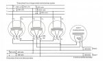
5 wire has 2 phases 90 degrees apart, but with a common center tap. Relative to this center neutral, you have 4 'hot' wires at 0, 90, 180, and 270 degrees. (Lets not revisit the 180 degree phase difference being a different phase or the same phase :) :) :) )

My guess is that 5 wires lets you feed both 240V 2 phase loads such as motors, and also provides 120V L-N for receptacles and lights (much as modern 208/120V wye three phase is used).

3 wire was also used, with your two phases 90 degrees apart and a common wire.

-Jon
 

mbrooke

Batteries Included
Location
United States
Occupation
Technician
5 wire has 2 phases 90 degrees apart, but with a common center tap. Relative to this center neutral, you have 4 'hot' wires at 0, 90, 180, and 270 degrees. (Lets not revisit the 180 degree phase difference being a different phase or the same phase :) :) :) )

My guess is that 5 wires lets you feed both 240V 2 phase loads such as motors, and also provides 120V L-N for receptacles and lights (much as modern 208/120V wye three phase is used).

3 wire was also used, with your two phases 90 degrees apart and a common wire.

-Jon

Are 120 and 240 the only voltages? I'd imagine 90* gives something strange like the square root of two.
 

winnie

Senior Member
Location
Springfield, MA, USA
Occupation
Electric motor research
Are 120 and 240 the only voltages? I'd imagine 90* gives something strange like the square root of two.

Yes, you also have the L-L voltage which would be root 2 * the L-N voltage. I suspect that this voltage was not used, in much the same way that the 208V 'wild leg' L-N voltage in a delta system wouldn't (shouldn't? isn't commonly?) used.

-Jon
 

mbrooke

Batteries Included
Location
United States
Occupation
Technician
Yes, you also have the L-L voltage which would be root 2 * the L-N voltage. I suspect that this voltage was not used, in much the same way that the 208V 'wild leg' L-N voltage in a delta system wouldn't (shouldn't? isn't commonly?) used.

-Jon

Don't think I've seen anything take 170 volts.
 

synchro

Senior Member
Location
Chicago, IL
Occupation
EE

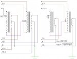
Shouldn't the equation for the neutral current "In" at the bottom right corner of the drawing be √(Ia2 + Ib2) instead of √(Ia2 - Ib2)? So if Ia and Ib are equal then the neutral current would be √2≈1.414 higher than each of them.
 
Status
Not open for further replies.
Top