You are using an out of date browser. It may not display this or other websites correctly.
You should upgrade or use an alternative browser.
You should upgrade or use an alternative browser.
62 amps short circuit current?
- Thread starter mbrooke
- Start date
- Status
- Not open for further replies.
Sadly, I have to agree. This is rather common in long runs...
I'm prepared to debate that.
The thing is they already know, hence why GFCIs and special-purpose GFCIs are gradually being mandated even in applications where historically missing EGCs have not been common.
Not unless you condense everything to a simple table, with a simple equation like Zs=Ze+(R1+R2). Which is what I'm trying to do for electricians, but, well, I need help.
The bigger issue is the NFPA mandating AFCIs and GFCIs to fix an issue that either doesn't exist or can be solved with simple math.

AFCIs are mandated to fix arcing faults which is popular with insurance companies but unproven technology. The big reason it is pushed at least originally was by one manufacturer. It’s a racket. GFCI was added because it’s low cost and makes the breaker far more likely to work in real circumstances.
I’ve worked extensively in mining and medium voltage where ground fault is front and center. With regards to ground fault the most effective way to make it work is by monitoring common mode current, essentially V1+V2(+V3) should add to zero in theory. So in theory we just pick a low limit like say 3-5 mA and trip on that. Perhaps we increase the limit with voltage. That’s the simple idea behind GFCI. Outside of 15 A residential only circuits this concept breaks down. First even with residential most pool pumps will trip a standard GFCI almost immediately. The reason is most have switching electronic motor drives. Take a look at this chart.
Hmm...NOT good. That’s common mode voltage from a VFD. Any time you take a simple single phase VFD and plug it into a GFCI...trip! Same thing with a UPS or really any switching system with the cheap $19 naive GFCI approach. And by the way an AFCI is looking for an arcing fault.
Hmm...square waves. Doesn’t this look like, well...switching power supplies? Yep...AFCIs have to somehow trip on arcing faults but not laptops or UPSs or variable speed motorized devices...
Oh but wait, it gets better. Ever heard of system capacitance or transmission line shunt capacitances or series inductance? With electrically long lines, higher voltages, and other conditions our nice pretty view of even “simple” wiring goes out the window. No switching power supplies needed! I think NEC has tried to rewrite the ground fault rule for switchgear on every single Code cycle and has managed to prove that it is an impossible situation short of mandating doing a full short circuit engineering study that they have not been willing to do either because they are unwilling to go to war with the engineering lobbyists or because it’s not something you can do with simple equations. Bussmann did a fantastic job with their point to point method but it still isn’t accepted.
While I would agree conceptually with “simple” models, this problem is not simple. GFCIs have been a nightmare. They “don’t work” at higher voltages as these other issues that you don’t see with home appliances show up quickly in industrial and commercial installations.
That is not necessarily true. The available short circuit currents calcs are way conservative. So 60 amps might really be 40 amps and that might take minutes or hours to trip.
No matter what the code explicitly requires an effective ground fault. This is not an effective gf path so is not code compliant.
What makes it an effective ground fault? What us the minimum current or minimum impedance? NEC doesn’t define this. I can easily detect and trip on this. Bender makes some reasonably priced relays for this purpose. I’m sure there are others. A GFCI would work, too. I see no issues with detecting a 62 A ground fault, let alone 40 A.

Bender North America
Bender Inc. – leaders in electrical safety & energy management. Explore products & solutions!
Really it comes down to what is acceptable leakage currents...what is just “normal” unbalanced or common mode currents we can safely ignore and what constitutes a fault that we need to trip on.
Plus if you live in North America and mostly work low voltage (under 1,000 V) chances are you have zero experience with anything other than solidly grounded systems. But that is not the case in other parts of the world or in higher voltages and certain industries. The idea of having an obscene amount of ground fault current as “safe” is just plain nuts.
Say I run a high resistance grounding system with a maximum of 25 A on a 4160 system. That means the resistor connected between the transformer neutral and ground is 96 ohms. If you grind through the math it works out to 94 mA for a touch current. This is going to hurt a LOT but is just shy of the 95 mA necessary to cause fibrillation. In other words you can touch a 4160 system and as long as it trips so that you can free yourself (we are above the let go threshold) you will survive it.
So gong back to my earlier statement...no reason that we can’t install systems that both minimize damage (25 A of fault current won’t cause an arc flash and blow things up) and drastically reduce the potential for a fatality. We can thank our European neighbors for tons of experience in installing such systems and proving that they work. They are very effective. Many even reduce the fault currents well below 25 A. I just picked a value that won’t burn up a 14 gauge wire and won’t kill someone from a ground fault. Typical trip setting is 60% of the maximum ground fault current or 15 A in this example, plenty high enough to ignore those pesky switching power supplies.
Let us first see what the maximum length for your branch circuit is per industrial practice if there is one.
If you knew anything about it you wouldn’t just throw out that comment. There is no standard. What “industrial practice” are you talking about and if you read OPs example you would know what the length is.
Unlike you I happen to know what the limitations are. The calculations are far more complicated though.
Long ago a table of maximum lengths for conduit was put out there with ZERO engineering behind it that we know of (no source, formula, etc.). The table of allowable conduit lengths for effective grounding got passed around some contract engineering firms but none of them know if it was valid or where it came from, Since then though the idea has been validated and extended.
None of the Codes have adopted it yet as a standard. It’s sort of up to the engineers/contractors to figure out what an effective ground path is. Few of them have a clue.
mbrooke:The branch circuit length may be checked per the table mentioned in the above comment.If you knew anything about it you wouldn’t just throw out that comment. There is no standard. What “industrial practice” are you talking about and if you read OPs example you would know what the length is.
Unlike you I happen to know what the limitations are. The calculations are far more complicated though.
Long ago a table of maximum lengths for conduit was put out there with ZERO engineering behind it that we know of (no source, formula, etc.). The table of allowable conduit lengths for effective grounding got passed around some contract engineering firms but none of them know if it was valid or where it came from, Since then though the idea has been validated and extended.
None of the Codes have adopted it yet as a standard. It’s sort of up to the engineers/contractors to figure out what an effective ground path is. Few of them have a clue.
mbrooke
Batteries Included
- Location
- United States
- Occupation
- Technician
Let us first see what the maximum length for your branch circuit is per industrial practice if there is one.
450 feet. NFPA-70 does not limit a circuit's maximum length.
No It violates 250.4A(5) because arbitrary long circuit does not ensure low circuit resistance path to facitate operation of protective device.450 feet. NFPA-70 does not limit a circuit's maximum length.
mbrooke
Batteries Included
- Location
- United States
- Occupation
- Technician
No It violates 250.4A(5) because arbitrary long circuit does not ensure low circuit resistance path to facitate operation of protective device.
Does it? The breaker still trips. So therefore, it meets the requirements.
Yes. The low resistance circuit parh is the criterion by the code. Clearly a circuit length as long as you like may not meet the code criterion. That is why there is a maximum circuit length for a given conductor size.Does it? The breaker still trips. So therefore, it meets the requirements.
mbrooke
Batteries Included
- Location
- United States
- Occupation
- Technician
Yes. The low resistance circuit parh is the criterion by the code. Clearly a circuit length as long as you like may not meet the code criterion. That is why there is a maximum circuit length for a given conductor size.
Low resistance is relative. 2 ohms will still trip a breaker, its less than 5 mego ohms, yet it can still harm someone touching a metal light pole.
NFPA-70 does not specify a max circuit length, breaker trip time or ohm value.
It is because NEC is not a design manual.NFPA-70 does not specify a max circuit length, breaker trip time or ohm value.
mbrooke
Batteries Included
- Location
- United States
- Occupation
- Technician
It is because NEC is not a design manual.
Practical safety is not design.
I think a proper design will take care of it.Low resistance is relative. 2 ohms will still trip a breaker, its less than 5 mego ohms, yet it can still harm someone touching a metal light pole.
mbrooke
Batteries Included
- Location
- United States
- Occupation
- Technician
AFCIs are mandated to fix arcing faults which is popular with insurance companies but unproven technology. It’s a racket. GFCI was added because it’s low cost and makes the breaker far more likely to work in real circumstances.
Are arcing faults even starting fires? What proof is there that a breaker opening in 25 cycles vs 3 cycles will reduce the probability of fire other than wrapping zip cord with highly flammable glass tape connected to a neon gas transformer in a lab setting?
The big reason it is pushed at least originally was by one manufacturer.
I'll agree day and night on this.
")
I’ve worked extensively in mining and medium voltage where ground fault is front and center. With regards to ground fault the most effective way to make it work is by monitoring common mode current, essentially V1+V2(+V3) should add to zero in theory. So in theory we just pick a low limit like say 3-5 mA and trip on that. Perhaps we increase the limit with voltage. That’s the simple idea behind GFCI. Outside of 15 A residential only circuits this concept breaks down. First even with residential most pool pumps will trip a standard GFCI almost immediately. The reason is most have switching electronic motor drives. Take a look at this chart.
Bigger issue: Xc=1/2pifC
Even a small yet sharp transient will cause an avalanche of current between current carrying conductors and anything metal referenced to earth or an EGC.
Hmm...NOT good. That’s common mode voltage from a VFD. Any time you take a simple single phase VFD and plug it into a GFCI...trip! Same thing with a UPS or really any switching system with the cheap $19 naive GFCI approach. And by the way an AFCI is looking for an arcing fault.
Is this because of capacitive coupling to ground or saturation of the torroid coil? I'm confused

Hmm...square waves. Doesn’t this look like, well...switching power supplies? Yep...AFCIs have to somehow trip on arcing faults but not laptops or UPSs or variable speed motorized devices...
And that is one out of many issues involving AFCIs. They lack any legit computing power capable of discriminating between ripple/sine wave distortion vs supposed dangerous arcing. Show me this pink unicorn you speak of, I want to see it!

Oh but wait, it gets better. Ever heard of system capacitance or transmission line shunt capacitances or series inductance? With electrically long lines, higher voltages, and other conditions our nice pretty view of even “simple” wiring goes out the window. No switching power supplies needed!
Easy 1) The NESC gives you discretion. No specific device are mandated. Even NERC/FERC has leeway despite what I'd say about it... 2) Arc detection devices used at the distribution and transmission level are light years ahead in theory, development, computing power, customer support and diagnostics. Not something you will ever acheive from $35 AFCI device. Perhaps decades from now, but not today.
I think NEC has tried to rewrite the ground fault rule for switchgear on every single Code cycle and has managed to prove that it is an impossible situation short of mandating doing a full short circuit engineering study that they have not been willing to do either because they are unwilling to go to war with the engineering lobbyists or because it’s not something you can do with simple equations. Bussmann did a fantastic job with their point to point method but it still isn’t accepted.
Technically you don't need an exact figure. Simple tables giving reasonable worse case scenarios (+/- 10%) will do. As long as the final results give a short circuit current higher (than actual) when determining AIC and a short circuit values lower (than actual) when determining breaker disconnect times we are all set.
Something as simple as assuming 75*C conductor temps for disconnection times and 30*C conductor temps for short circuits might actually get the job done. No different than what we do know when sizing conductors with table 310.16...
While I would agree conceptually with “simple” models, this problem is not simple. GFCIs have been a nightmare. They “don’t work” at higher voltages as these other issues that you don’t see with home appliances show up quickly in industrial and commercial installations.
At higher voltages you can set your zero sequence pickup magnitude, phase angle, time curve, ect any way you want it even feeding it through timers, boolean logic ect... heck even a lenticular MHO with binders and what if you're dealing with a 311C or 421... you can do most anything with an SEL relay.
However, in the NEC world you are typically stuck certain values, either 5ma born out of litigation or 30ma out of the IEC body graph.
5ma has work reasonably well (with refinement along the way) for point of use GFCI protection. However the code wants to implement either 5 or 30ma on all circuits instead of clarifying or putting numbers to what they mean when they say "effective ground fault current path"
The thing is the CMPs know they made a mistake in not defining it. They now know ground rods don't open breakers. They now know an EGC must be sized sufficiently, not just present like previously assumed. Instead of fixing the root error, they are using this as an opportunity to mandate more products and services which by design wittingly self lockout in a few years.
mbrooke
Batteries Included
- Location
- United States
- Occupation
- Technician
I think a proper design will take care of it.
Sure. But what am I aiming for?
You are aiming for code proposals, I believe.Sure. But what am I aiming for?
mbrooke
Batteries Included
- Location
- United States
- Occupation
- Technician
You are aiming for code proposals, I believe.
If those would actually do anything.
What would you propose?
Honest question mbrooke
Batteries Included
- Location
- United States
- Occupation
- Technician
What makes it an effective ground fault? What us the minimum current or minimum impedance? NEC doesn’t define this. I can easily detect and trip on this. Bender makes some reasonably priced relays for this purpose. I’m sure there are others. A GFCI would work, too. I see no issues with detecting a 62 A ground fault, let alone 40 A.
Electronics can and do fail.
This leaves us with a thermal-magnetic device or fuse.
62 amps will trip a 20 amp breaker. But thats only half the story.
Consider the restive divider which forms during the fault. 60 volts to earth on a 120 volt system, 138 volts on a 277 volt system.
How well does the human body tolerate this voltage for 30 seconds? A few minutes? On a child?
I give you this:

Log-log graph of the effect of alternating current I of duration T passing from left hand to feet as defined in IEC publication 60479-1.[21]
AC-1: imperceptible
AC-2: perceptible but no muscle reaction
AC-3: muscle contraction with reversible effects
AC-4: possible irreversible effects
AC-4.1: up to 5% probability of ventricular fibrillation
AC-4.2: 5-50% probability of fibrillation
AC-4.3: over 50% probability of fibrillation
To which UL has copied as their own:
Consulting - Specifying Engineer | UL’s new GFCI classes
Consulting - Specifying Engineer - Learning objectives Understand UL’s new GFCI classes. Understand how GFCIs for 240 to 600 V applications differ from the familiar Class A GFCIs. Know
 www.csemag.com

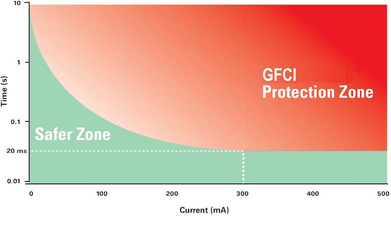
The trip curve published by UL for GFCIs was designed to keep current through the body to safe levels, prescribing GFCI trip times that decrease with increasing current, as defined by the equation, where T is in sec and I is in mA, and shown in Figure 3. Note that at currents greater than 300 mA, the delay is fixed at 20 msec.
Not UL's curve, not their research, nothing new is being presented.
Also:
Is this really how manufacturing reps sitting in those CMP seats really want to define "effective ground fault current path"?
mbrooke
Batteries Included
- Location
- United States
- Occupation
- Technician
My proposal: Make NEC more design friendly.
Of course it is vague.
Not vague. The NEC in its modern forum punishes and addles the user. You can not solve problems with the same thinking which created them in the first place. (not directed at you Sahib)
- Status
- Not open for further replies.