705.12(B)(3)(6)

Gridtied

Member
Location
Colorado
Occupation
Electrician
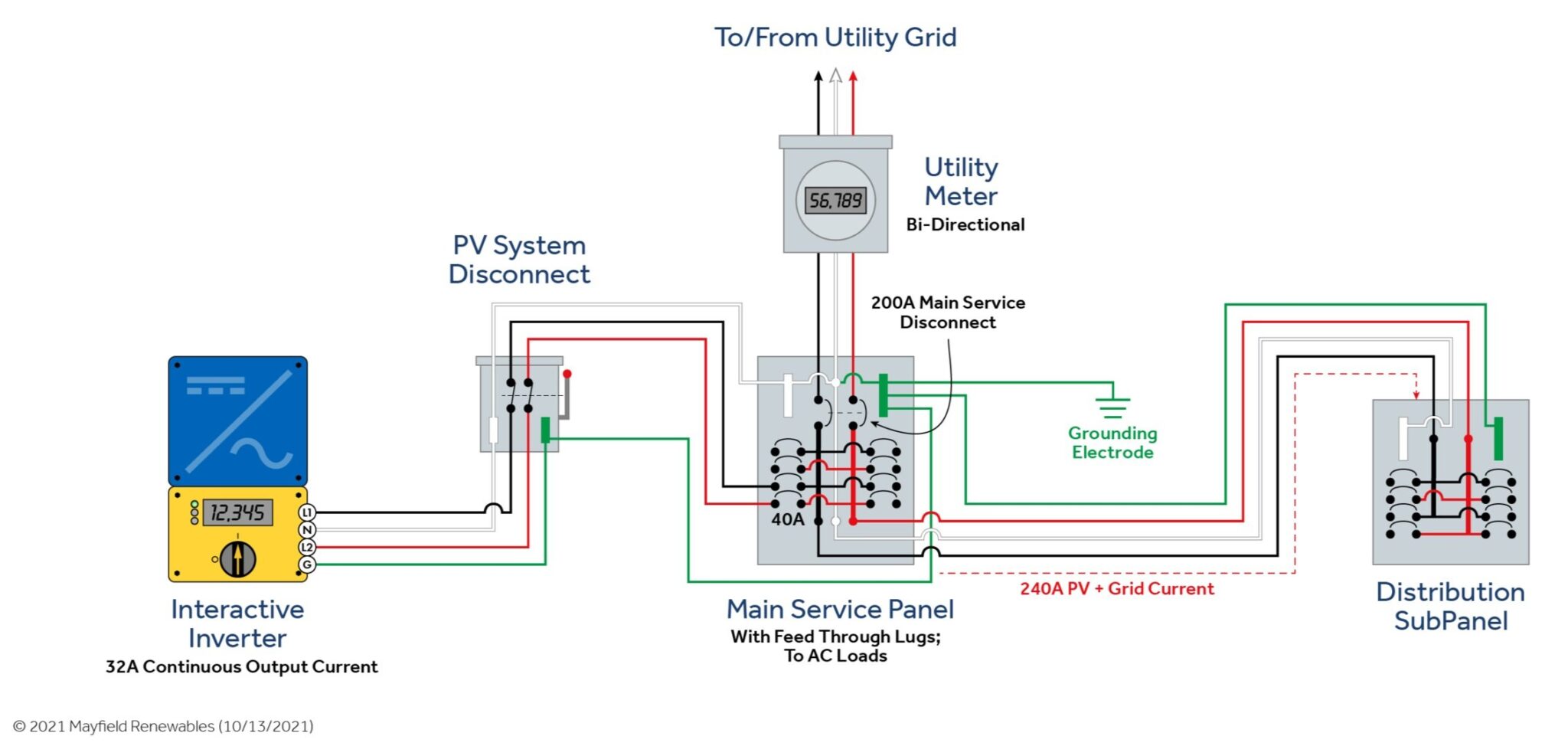
I need a little help on this 2020 NEC 705.12(B)(3)(6). I am reviewing plan sets where the customer has a 200A MMC with a 150A MB and feed through lugs that feed a 200A ML panel through 3/0 AL @ 155A. The customer wants to add a 40A CB for the PV (31.05A x 125% = 38.8A) to the ML panel. The meter/main currently does not have loads in it, but could have them added later. I believe that an OCPD is needed t either end of the 3/0 AL feeder to protect the feeder. I saw a video from Mayfield renewables that does a decent job of explaining a similar scenario, but only when the POC is in the MMC. The 2023 NEC seems to agree with my interpretation, but the 2020 NEC just seems to lean towards the POC in the MMC. See the image below, but move the PV POC to the distribution panel.
MayfieldRenewablesNEC705.12B36a-scaled.jpg
 

wwhitney

Senior Member
Location
Berkeley, CA
Occupation
Retired
Seems like the proposed arrangement is OK under 705.12(B)(3)(1). If you have 150A from the utility, and 40A (after 125%) from the PV, then any bus that is rated 200A will qualify under that section. No need to read any further into 705.12(B)(3).

Cheers, Wayne
 

Gridtied

Member
Location
Colorado
Occupation
Electrician
Seems like the proposed arrangement is OK under 705.12(B)(3)(1). If you have 150A from the utility, and 40A (after 125%) from the PV, then any bus that is rated 200A will qualify under that section. No need to read any further into 705.12(B)(3).

Cheers, Wayne
How about the feeders between the 2 panels only being rated for 155A? I am seeing similar situations with a 200A MB in the MMC to a 200A ML panel with 2/0 Cu or 4/0 AL and I feel that 705.12(B)(1) should be followed.
 

wwhitney

Senior Member
Location
Berkeley, CA
Occupation
Retired
How about the feeders between the 2 panels only being rated for 155A? I am seeing similar situations with a 200A MB in the MMC to a 200A ML panel with 2/0 Cu or 4/0 AL and I feel that 705.12(B)(1) should be followed.
Agreed, 705.12(B)(1) applies to the feeder, but the configuration complies. The first sentence of 705.12(B)(1) just says the feeder needs an ampacity of 40A. And as the power source output connection is made at the opposite end of the feeder from the primary power source connection, the rest of 705.12(B)(1) imposes no further requirements.

Cheers, Wayne
 

ggunn

PE (Electrical), NABCEP certified
Location
Austin, TX, USA
Occupation
Consulting Electrical Engineer - Photovoltaic Systems
Seems like the proposed arrangement is OK under 705.12(B)(3)(1). If you have 150A from the utility, and 40A (after 125%) from the PV, then any bus that is rated 200A will qualify under that section. No need to read any further into 705.12(B)(3).

Cheers, Wayne
In the drawing the MCB in the main panel is 200A. Either the feeder to the subpanel and the subpanel itself have to be rated at minimum 240A or there has to be OCP ahead of the subpanel rated to protect the feeder and subpanel.
 

jaggedben

Senior Member
Location
Northern California
Occupation
Solar and Energy Storage Installer
It also makes a difference that the text said that the feeder connected to the feed through lugs is 3/0 AL, which the OP correctly notes is rated only 155A. So the situation is, in fact the same as in the diagram, just with different numbers. And an OCPD at one end or the other of the feeder to the sub is necessary to protect the feed through wiring.
 

Elect117

Senior Member
Location
California
Occupation
Engineer E.E. P.E.
I agree with Jaggedben, you should protect the 3/0 at it's ampacity at the downstream panel or by installing a fused d/c between the main and the downstream panel.

Or replace the 3/0 aluminum with 3/0 copper.

Your example would have the math being a possible 150A from utility and 40A from the solar. That is less than 200A so the boards are okay but that 3/0 will not be.
 

wwhitney

Senior Member
Location
Berkeley, CA
Occupation
Retired
Your example would have the math being a possible 150A from utility and 40A from the solar. That is less than 200A so the boards are okay but that 3/0 will not be.
Again, why? It's 150A from the utility at one end, and 40A from PV at the other end. It complies with 705.12(B)(1) without any additional OCPD.

If it were 150A at one end, 40A in the middle, and loads at the far end, then yes, 705.12(B)(1) would require additional OCPD. But it's not (per the OP; the diagram is inaccurate. From the OP: "See the image below, but move the PV POC to the distribution panel.")

Cheers, Wayne
 

jaggedben

Senior Member
Location
Northern California
Occupation
Solar and Energy Storage Installer
Again, why? It's 150A from the utility at one end, and 40A from PV at the other end. It complies with 705.12(B)(1) without any additional OCPD.

If it were 150A at one end, 40A in the middle, and loads at the far end, then yes, 705.12(B)(1) would require additional OCPD. But it's not.

Cheers, Wayne
Perhaps you are missing that the solar is connected in the main. So the utility and solar feed are both at one end of the 3/0 AL feeder, and the load is at the other.
 

Elect117

Senior Member
Location
California
Occupation
Engineer E.E. P.E.
Again, why? It's 150A from the utility at one end, and 40A from PV at the other end. It complies with 705.12(B)(1) without any additional OCPD.

If it were 150A at one end, 40A in the middle, and loads at the far end, then yes, 705.12(B)(1) would require additional OCPD. But it's not (per the text; the diagram is inaccurate.)

Cheers, Wayne

The 3/0 is installed between the two panels. That is 155A connecting two 200A boards. All the load is on the downstream board. 150A breaker protects both boards (if no solar is installed) so the 3/0 doesn't need OCPD.

Add solar

Now we are over 155A at the down stream board.

Utility breaker no longer protecting the 3/0.

Add breaker or fuses to protect existing 3/0 or replace to have higher ampacity than both sources.
 

wwhitney

Senior Member
Location
Berkeley, CA
Occupation
Retired
Perhaps you are missing that the solar is connected in the main. So the utility and solar feed are both at one end of the 3/0 AL feeder, and the load is at the other.
Perhaps you are missing the part of the OP that says the diagram is not accurate; see the OP text and post #11.

Cheers, Wayne
 

wwhitney

Senior Member
Location
Berkeley, CA
Occupation
Retired
Now we are over 155A at the down stream board.

Utility breaker no longer protecting the 3/0.

Add breaker or fuses to protect existing 3/0 or replace to have higher ampacity than both sources.
The sources can't add, it's 150A possible supply at one end, and 40A possible supply at the other ends. No way for the wire to see more than 150A. It complies with 705.12(B)(1) and no additional OCPD is required.

Cheers, Wayne
 

jaggedben

Senior Member
Location
Northern California
Occupation
Solar and Energy Storage Installer
Perhaps you are missing that the solar is connected in the main. So the utility and solar feed are both at one end of the 3/0 AL feeder, and the load is at the other.
Nevermind (maybe).
The original text said they want to connect the solar to the subpanel, which is unlike what the diagram shows. If the text is correct and the diagram is wrong, then I agree with you. (If the diagram is correct and the text is wrong, then what I said before.)

Edit: typing at the same time. Lol
 

wwhitney

Senior Member
Location
Berkeley, CA
Occupation
Retired
Nevermind (maybe).
The original text said they want to connect the solar to the subpanel, which is unlike what the diagram shows. If the text is correct and the diagram is wrong, then I agree with you. (If the diagram is correct and the text is wrong, then what I said before.)
Seeing as how the text says "See the image below, but move the PV POC to the distribution panel," we can be confident the diagram is not accurate.

Cheers, Wayne
 

Elect117

Senior Member
Location
California
Occupation
Engineer E.E. P.E.
Wayne and the fine print lol.

I read it as he is putting the solar in the main. But that is also because MMC and ML are similar lol.

"The 2023 NEC seems to agree with my interpretation, but the 2020 NEC just seems to lean towards the POC in the MMC. See the image below, but move the PV POC to the distribution panel."

I took it as he didn't know where to make the POC and was talking about putting it like the photo.

Whatever.

Wayne is right if the POC is in the sub panel.
 

wwhitney

Senior Member
Location
Berkeley, CA
Occupation
Retired
Yeah, including that diagram really confused me. It represents a totally different situation.
Yes, the inaccurate diagram makes the OP a reading comprehension minefield. If you're not going to mark up the diagram to correct it, better to omit the diagram altogether and just include a textual one line:

Utility
Meter/main/distribution with 150A OCPD and 200A busbar
Feed thru lugs
3/0 Al conductors
MLO 200A panel
Loads plus 40A PV interconnection

Cheers, Wayne
 
Last edited:
Top