You are using an out of date browser. It may not display this or other websites correctly.
You should upgrade or use an alternative browser.
You should upgrade or use an alternative browser.
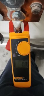
.8 amps/Dangerous?
- Thread starter pauld
- Start date
Master Nater
Senior Member
- Location
- Midwest
- Occupation
- Electrical Magician
what are we looking at here? amperage on a grounding electrode?
if so, you need to understand that electricity takes ALL PATHS AVAILABLE. not the misinformation that we've all heard about taking the path of least resistance.
so, on any system, there will be current flow on the GEC. it just dpeneds upon how low the resistance on the grounding electrode system is, versus what the resistance is on the service grounded conductor. this COULD be an indicator of a system neutral getting weak, but not neccessarily. what is the amperage on the neutral to compare to?
curt swartz
Senior Member
- Location
- San Jose, CA
- Occupation
- Electrical Contractor
Having current on the GEC's is very normal especially if there are multiple services connected to the metal underground water service.
- Location
- New Jersey
- Occupation
- Journeyman Electrician (retired)
Nothing to address. As others have stated this is perfectly normal.Ran into this on a building today should be addressed immediately
winnie
Senior Member
- Location
- Springfield, MA, USA
- Occupation
- Electric motor research
IMHO I'd ask a few questions before declaring this perfectly normal.
1) Are we looking at current flowing to water pipe bond, to a couple of ground rods, or to something else?
2) How large of a service are we looking at?
If I saw 0.8A flowing into a typical ground rod at a residence, I'd want to dig further. That current would imply significant voltage on the neutral given the typical ground rod resistance.
If I saw 0.8A flowing into to a water pipe ground in an urban residence (where common underground piping is typical) then I wouldn't be concerned at all; the underground pipes are a metallic connection parallel to the neutral.
If I saw 0.8A flowing to a water pipe bond at a location where the underground water piping was insulated, I'd be very concerned; that 0.8A implies some sort of ground fault in the facility.
If I saw 0.8A flowing to a large grounding electrode system at a big industrial plant with a huge service I wouldn't be concerned at all.
(And note: I am familiar with theory and the above is based on that. I am not a professional electrician.)
EngineeredElectric
Member
- Location
- Lockport IL
- Occupation
- Contractor
I'm with Winne. More info needed.
- Location
- New Jersey
- Occupation
- Journeyman Electrician (retired)
Since from the photo that appears to be a #4/0 conductor bolted to a large ground bus in what is probably a commercial building I'm surprised it's only .8 amps.
electrofelon
Senior Member
- Location
- Cherry Valley NY, Seattle, WA
- Occupation
- Electrician
I was just going to post the same thing, seems low actually.Since from the photo that appears to be a #4/0 conductor bolted to a large ground bus in what it probably a commercial building I'm surprised it's only .8 amps.
- Location
- New Jersey
- Occupation
- Journeyman Electrician (retired)
I agree. I did a little experiment on my own water pipe. Test clamp has a conversion of 1mA/A. First test indicated about .33 amps with the normal house load and the clamp directly around the pipe where it exits the foundation. Then I turned on a heat gun with a 120 volt load of about an 8.5 amps and the current on the pipe shot up to .89 amps.I was just going to post the same thing, seems low actually.
You mathematicians can probably estimate about how much of the current is flowing on the pipe under normal conditions.


winnie
Senior Member
- Location
- Springfield, MA, USA
- Occupation
- Electric motor research
Exactly. There are very common situations where multiple amps on a GEC is totally expected and a normal consequence of the system design. The issue of current on underground water systems is not a problem until a plumber needs to cut the pipe.
This is why I'd hope the OP comes back and describes exactly what line they are measuring. I agree with @infinity and @electrofelon that based on the picture this is probably a nothing burger, but would like to know more.
This is why I'd hope the OP comes back and describes exactly what line they are measuring. I agree with @infinity and @electrofelon that based on the picture this is probably a nothing burger, but would like to know more.
If I am reading that right it appears to say 'mA' so 0.33 mA = 0.33 / 1000 A = 0.00033 AmpsI agree. I did a little experiment on my own water pipe. Test clamp has a conversion of 1mA/A. First test indicated about .33 amps with the normal house load and the clamp directly around the pipe where it exits the foundation. Then I turned on a heat gun with a 120 volt load of about an 8.5 amps and the current on the pipe shot up to .89 amps.
You mathematicians can probably estimate about how much of the current is flowing on the pipe under normal conditions.
View attachment 2582316View attachment 2582317
- Location
- New Jersey
- Occupation
- Journeyman Electrician (retired)
I mentioned in post #9 that the clamp has a 1 mA to 1 amp conversion factor. Here's a test photo where I tested the meter first with a heat gun. 8.52 mA = 8.7 amps. There's an obvious small margin of error with one or both of the measurements.If I am reading that right it appears to say 'mA' so 0.33 mA = 0.33 / 1000 A = 0.00033 Amps

Low setting on gun.

wwhitney
Senior Member
- Location
- Berkeley, CA
- Occupation
- Retired
Reread the second sentence of infinity's post.If I am reading that right it appears to say 'mA' so 0.33 mA = 0.33 / 1000 A = 0.00033 Amps
Cheers, Wayne
wwhitney
Senior Member
- Location
- Berkeley, CA
- Occupation
- Retired
So that's a delta of either 1.22A or of 0.56A, depending on sign (you could do the test twice, with the 120V load on each of the two legs, to differentiate). Which says that the GEC path has an impedance in ratio to the intended grounded conductor path of either (8.5-1.22)/1.22 = 6.0 or (8.5 - 0.56) / 0.56 = 14.First test indicated about .33 amps with the normal house load and the clamp directly around the pipe where it exits the foundation. Then I turned on a heat gun with a 120 volt load of about an 8.5 amps and the current on the pipe shot up to .89 amps.
Cheers, Wayne
I see thanks I figured I missed something so @wwhitney you're saying the added test current on the pipe could be the same direction as the original pipe current or the opposite direction from the original pipe current? And there might be base current from the pipe to the neutral bar -.33A or current from the neutral bar to the pipe +.33A ?So that's a delta of either 1.22A or of 0.56A, depending on sign (you could do the test twice, with the 120V load on each of the two legs, to differentiate). Which says that the GEC path has an impedance in ratio to the intended grounded conductor path of either (8.5-1.22)/1.22 = 6.0 or (8.5 - 0.56) / 0.56 = 14.
Cheers, Wayne
And if thats correct @infinity could take a 2nd measurement of his total service neutral current at the same time as both readings;
If the pipe got 0.56 A of that, then the neutral total got about:
8.5 - 0.56 = 7.94 A
Or If the pipe got 1.22 A of that, then the neutral total got about:
8.5 - 1.22 = 7.28 A
wwhitney
Senior Member
- Location
- Berkeley, CA
- Occupation
- Retired
Let's say that if the only load is from L1 to N, then the neutral current is positive, while if the only load is from L2 to N, then the neutral current is negative. The meter only gives you the magnitude of the current, without the sign. You can think of positive and negative as from/to, although this is AC.I see thanks I figured I missed something so @wwhitney you're saying the added test current on the pipe could be the same direction as the original pipe current or the opposite direction from the original pipe current?
If the neutral current can only return on the grounded service conductor or the water pipe, no 3rd option, then there's two possibilities for infinity's measurements of the current on the water pipe:
Both the 0.33 and the 0.89 have the same sign. So the change is 0.56A, out 8.5A of new load. That means the resistance ratio is (8.5-0.56)/0.56 = 14. If we had measured grounded service conductor current at the same time as the water pipe, it would have read 14 * 0.33 = 4.7A and 14 * 0.89 = 12.6A, respectively.
Or the 0.33 and 0.89 have different signs. So the change is 1.22A, our of 8.5A of new load. That means the resistance ratio is (8.5-1.22)/1.22 = 6.0. If we had measured grounded service conductor current at the same time as the water pipe, it would have read 6.0 * 0.33 = 2.0A and 6.0 * 0.89 = 5.3A, respectively.
Yes, but in the first case, the 7.94A is the difference of the two service neutral current measurements (12.6 - 4.7 in the above), while in the second case, the 7.28A is the sum of the two service neutral current measurements (5.3 + 2.0 in the above), because the meter is only giving us magnitude and not sign.If the pipe got 0.56 A of that, then the neutral total got about:
8.5 - 0.56 = 7.94 A
Or If the pipe got 1.22 A of that, then the neutral total got about:
8.5 - 1.22 = 7.28 A
Cheers, Wayne