A simple resistance capacitor circuit

Status
Not open for further replies.

gar

Senior Member
Location
Ann Arbor, Michigan
Occupation
EE
161029-2142 EDT

Given two simple transient circuits how would you determine the T=0 input current to the circuit, and output voltage across the capacitor for each circuit? The T=infinity values of current and voltage? And the time t for the output voltage to reach 63.2% of its final value?

The input voltage is a step change of voltage from 0 to +1 V. The initial capacitor voltage is 0 V.

The first circuit is a simple series circuit consisting of a 1 megohm resistor and 1 mfd capacitor.

The second circuit is the same as the first except that a 1/2 megohm resistor is shunted across the capacitor.

Describe your approach as well as the numeric answers.

For those of you that this is "duck soup" don't answer until others have had a chance.

.
 

junkhound

Senior Member
Location
Renton, WA
Occupation
EE, power electronics specialty
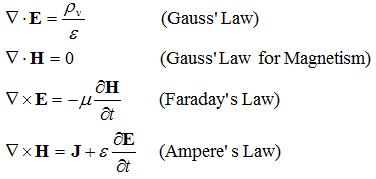
And to be left for the student, derive the simple exponential equatins from the following basics :lol:<G>
maxwellseq.jpg
 

rian0201

Senior Member
Location
N/A
A simple resistance capacitor circuit

This is an assignment.. Hihi


Sent from Mars
 
Last edited:

gar

Senior Member
Location
Ann Arbor, Michigan
Occupation
EE
161030-1409 EDT

I created this question(s) such that the answers are simple and can be calculated in your head. This is not a trick type of question. With some thought I believe that many ordinary electricians, with some basic circuit theory education, can answer at least part of the question. The purpose of the question is to stimulate thought.

The second circuit is designed to evoke thought on how to approach a solution.

If 1 megohm is changed to 1 k, then experimentally the circuit operation can be easily viewed on an oscilloscope.

A different question is: Ohm had an idea (theory). How did he perform experiments to prove his theory. What a priori information was available to him? How did he measure, current, voltage, and resistance (conductance)? How did he produce an adjustable voltage source. Note that power equations are not part of Ohm's law. If you could not buy an ammeter, then how could you measure current? How did Edison measure current and in turn energy use?

.
 

junkhound

Senior Member
Location
Renton, WA
Occupation
EE, power electronics specialty
And how did Volta measure voltage ?

Hint: there was no OSHA at that time :happyno:


Could not find and open source pdf of the article, from IEEE spectrum sometime in the 70's
"Volta as Voltmeter" Think all IEEE members can access online thru IEEExplore.
 
I feel like this question is either trivaly easy if you know the formulas or impossible if you do not. I do not think you will get anwsers from people who do not fall into the duck soup catagory.
 

Ingenieur

Senior Member
Location
Earth
I feel like this question is either trivaly easy if you know the formulas or impossible if you do not. I do not think you will get anwsers from people who do not fall into the duck soup catagory.

It is pretty straight forward if you had basic college level math/physics/circuits
it is fundemental for transient study (along with LR and LC ckts)
 

junkhound

Senior Member
Location
Renton, WA
Occupation
EE, power electronics specialty
.. transient study....with LR and LC .....

In Seattle area, every 3rd Friday AM between 2AM and 5 AM there is a transient study and count, 19% increase last year..hmm, = about 1/2e, .. is LR and LC anything like LGBT ? Not sure how to count that here.

Thought of putting a 'natural log' (or 1/e) under blankets in the back of the truck and parking it on the street ....
 

gar

Senior Member
Location
Ann Arbor, Michigan
Occupation
EE
161039-1932 EDT

Ultrafault:

The answers for t = 0+ and infinity should be easy for many electricians. For an intermediate time this may be more difficult. But it can be a challenge to someone to learn some thing new.

I created this thread based on another thread where some responders were making guesses that did not correlate with the evidence.

A basic understanding of circuits is necessary to make troubleshooting efficient.

.
 
Good points. The key to t=0 is that the enegy in a capacitor is .5Cv^2 and you cannot have a instantaneous chane in energy. The key to t=inf is that a resistor with no current has no voltage drop.
 

gar

Senior Member
Location
Ann Arbor, Michigan
Occupation
EE
161031-0733 EDT

rian0201:

I don't know. Call it what you want. I defined the input as a step change in voltage. I suppose I could call it either AC or DC, but what difference does it make? If I put a spectrum analyzer on any of the waveforms present in the circuit I would see a multitude of frequencies.

.
 

Ingenieur

Senior Member
Location
Earth
first case:
Vc = V (1 - e^-kt) (derived from the 1st order diff eq solution from KVL or a Laplace/Laplace^-1)
V = 1
k =1/RC or 10^-3 where RC is the time constant
Vc starts at 0 (assuming no initial charge on cap) and rises exponentially to V (never gets there) but achieves 98% in 4 time constants
it gets to 63% (0.63 V) in 1 time constant or 1000 sec

second case:
basically the same exponential form except with a voltage divider
R2/(R1 + R2) x V
and
RC = Req x C
where Req = R1||R2

Vc = V across the parallel R2
 

gar

Senior Member
Location
Ann Arbor, Michigan
Occupation
EE
161031-0834 EDT

Ingenieur:

RC off by 1000. 1 meg, 1 mfd is 1 second.

Can some others provide the input currents for both circuits at t=0+ and infinity?

.
 

rlundsrud

Senior Member
Location
chicago, il, USA
I sincerely doubt the average electrician would have any idea how to answer this. Most electricians believe electrons travels at the speed of light in a conductor. Almost any engineer should be able to answer this as it is more of an engineering question.
 

gar

Senior Member
Location
Ann Arbor, Michigan
Occupation
EE
161031-0944 EDT

rlundsrud:

I believe that many "average electricians" are quite smart and have a reasonable knowledge of electrical circuit theory. In many industrial plants the electricans help uther trades solve the problems of the other trades.

Two things about the first circuit. A capacitor's voltage can not be instantaneoously changed, and under steady state conditions there is very little current flow thru a capacitor. For a good quality capacitor its leakage current might make its apparent resistance appear to be in excess of a 1000 megohms.

Thus, for the first circuit, since the initial capacitor voltage was 0 V at t=0-, then at t=0+ the load on the step voltage looks like just 1 megohm. Initial current is 1/1,000,000 = 1 microampere. Exactly the same condition exists for circuit 2.

At t= infinity the load on the voltage source is extremely high, namely the leakage resistance of the capacitor. Current load on the step voltage at this time is essentially 0.

It should be obvious to the average electriciab how to solve these two limit conditions for the second circuit.

I will agree that an average electrician is less likely know or understand the timing of the 63% point.

.
 

iwire

Moderator
Staff member
Location
Massachusetts
161031-0944 EDT

rlundsrud:

I believe that many "average electricians" are quite smart and have a reasonable knowledge of electrical circuit theory. In many industrial plants the electricans help uther trades solve the problems of the other trades.

I don't believe you have really been exposed to the average electrician. :D
 

junkhound

Senior Member
Location
Renton, WA
Occupation
EE, power electronics specialty
161031-0834 EDT
Can some others provide the input currents for both circuits at t=0+ and infinity?
.

Insufficient info: You did not provide a frequency for ac or dv/dt (rise time) of the dc 'square wave'; nor have you provided the ESR of the capacitor or the length of wire connecting everything and that wire's proximity to the return plane or wire.

Need the source impedance of the voltage source also:
Example: Stray wire = 3 uH each way, ESR = 10 milliohms, wire resistance 12 mohms each way, 10 microsecond rise time of the dc source, and source impedance of 2 mohms. Time of 0+ out to 100us.
Derivation of the equations is left to the student <G> Hint: use matlab or Pspice.
Long time ans = trivial.

Note: for those interested, you can reproduce the below yourself with one of the free online PSpice programs:
The below was run on orcad lite 16.6
These programs let you draw a schematic and then compute the circuit responses. The $6k version has nearly unlimited capability, our company provides a licensed version of the full capability program. You can design a VFD from scratch 'easily'.

Free versions - limited capabilities
Orcad: http://www.orcad.com/products/orcad-lite-overview?gclid=COqPsbWhhdACFZRffgodkkMD-g
Linear Tech: http://www.linear.com/designtools/software/

Presentation3.jpg
 

Ingenieur

Senior Member
Location
Earth
161031-0834 EDT

Ingenieur:

RC off by 1000. 1 meg, 1 mfd is 1 second.

Can some others provide the input currents for both circuits at t=0+ and infinity?

.

quote :
"The first circuit is a simple series circuit consisting of a 1 megohm resistor and 1 mfd capacitor"
1 mF = 10^-3
1 uF = 10^-6
???

I assumed 1 M Ohm and 1 mF or 10^6 x 10^-3 = 1000

I is basically the inverse
I = V/R (e^-t/RC)
 

gar

Senior Member
Location
Ann Arbor, Michigan
Occupation
EE
161031-1121 EDT

junkhound:

To study basic concepts the idealized circuits provided are sufficient, and would be typical of textbook, classroom, and patent circuits.


Ingenieur:

Both mfd and ufd have been used for microfarad for a longtime. But I will admit that 1M for 1k would be confusing today for a 1000 ohm resistor, and I can see why you would be confused my mfd.

.
 
Status
Not open for further replies.
Top