Adding Transfer Switch to Existing Service Disconnect

Status
Not open for further replies.
Location
Houston
Occupation
Electrician - Generator Installer

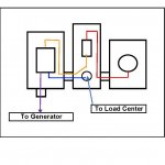
I have an existing Service Entrance with an externally mounted 200A Main Disconnect adjacent to the Utility Meter. The Disconnect feeds through the wall into the Load Center. I plan to install a Non-Service Rated 200A Transfer Switch on the outside wall adjacent to the existing Main Disconnect. According to code, I should be able run both the cables from the load side of the Main Disconnect (since they are protected by the Main Disconnect CB) and the cables feeding the Load Center from the Transfer Switch in the same raceway since they are considered feeder cables and not service cables. However, is it ok for me to run the feeder cables through the Main Disconnect Enclosure into the nipple connecting the Main Disconnect to the Load Center? ```
 
Welcome to the forum.

Yes. With the main disco outside, those are already feeder conductors, so nothing is really being changed.

Having an existing outside main and a four-wire feeder makes this so much easier. (y)
 
Last edited:
Thanks a lot Larry for your guidance. I tried to insert a simple one-line but couldn't figure out how to insert in this forum. Glad you got the idea from my description.
David Whisenhunt
Retired EPC Power Plant Contractor
 
You're welcome.

I did the same thing here. I had to butt-splice a few inches of wire to the original SER line conductors to reach the output terminals of the ATS:


KIMG0054.JPG KIMG0062.JPG
 
Thanks Larry,
Here's a simple one-line of what I plan to do. I'll replace the blue conductors between the transfer switch and Load Center across the wall so I don't have to splice.
Question: I've never used a Service Rated Switch when there was already a Main Disconnect. It looks like the Neutral is grounded in both locations. Did the inspector give you any problem with this?
 

Attachments

  • Middleton Generator One Line.jpg
    Middleton Generator One Line.jpg
    82.8 KB · Views: 20
You're welcome.

I did the same thing here. I had to butt-splice a few inches of wire to the original SER line conductors to reach the output terminals of the ATS:


View attachment 2561331 View attachment 2561332
Why did you not run the load side neutral into the ATS like the hots? Why the smaller neutral fed from the load side?
Why are there two GECs in the disconnect? One to water pipe or something?
 
Why did you not run the load side neutral into the ATS like the hots?
Because there was no reason to do so. It would have been a waste of time, material, and nipple area.

The only need for the neutral in the ATS at all is for the thin wire on the left end of the ATS's neutral bar.

Why the smaller neutral fed from the load side?
The two white wires on the ATS's neutral bar are from the genny, and to the top small lug on the disco's neutral bar.

Those two white-marked wires only carry current when the genny is supplying power, so it need be no bigger.

Why are there two GECs in the disconnect?
As above, one EGC is from the genny, and the other runs to the split bolt on the lower-left of the disco's neutral bar.

This was as convenient a way as any to bond the ATS's enclosure and the genny to the service neutral in the disco.

One to water pipe or something?
The two bare copper wires are the original electrode conductors.
 
Because there was no reason to do so. It would have been a waste of time, material, and nipple area.

The only need for the neutral in the ATS at all is for the thin wire on the left end of the ATS's neutral bar.


The two white wires on the ATS's neutral bar are from the genny, and to the top small lug on the disco's neutral bar.

Those two white-marked wires only carry current when the genny is supplying power, so it need be no bigger.


As above, one EGC is from the genny, and the other runs to the split bolt on the lower-left of the disco's neutral bar.

This was as convenient a way as any to bond the ATS's enclosure and the genny to the service neutral in the disco.


The two bare copper wires are the original electrode conductors.
Seems your genny would already be bonded through the neutral?
 
Status
Not open for further replies.
Top