Thanks for all the replies.
Sorry for the delay. Let me supply more info.
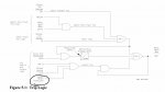
This is a simple transfer (throw-over) scheme that employs 2 MV vacuum breakers: Utility and Generator.
The logic is controlled by 2 Multilin relays: M60 and G60 (Main and Generator) and the SEL relay which I think is for redundant protection.
A power failure occurred, generator started, Main opened and Gen bkr closed.
Utility power returned, but instead of the Gen bkr opening and the Main bkr closing the Gen bkr stayed closed
and the LO alarm showed on the SEL and Failed To Transfer showed on the M60 and G60 relays.
I don't remember what I did to reset the alarms (this happened last year) but when I did, the Gen bkr immediately opened but the Main did not close. Found out later that the close spring charge circuit failed on the Main bkr (C-H VCP .) We manually charged the springs to get the Main bkr closed.
Our next step is to repair the charge circuit on the Main bkr or replace bkr with a spare that was just received.
Can someone answer how I was able to reset the alarms without accessing the program with a laptop.