Anyone has knowledge of Lead Sheath MV Cable?

Status
Not open for further replies.

zemingduan

Senior Member
Location
Philadelphia,PA
Occupation
Electrical Designer
We have a college campus project that need to splice new 5 KV MV-105 shielded conductor into existing 2.4KV three -conductor MV cable. The new 5KV MV cable will feed a new transformer for chiller. The existing 2.4KV three -conductor MV cable is a feeder run around 2000ft total in the tunnel all the way back to the 13.2KV -2.4KV substation in the campus. There are other 5 or 6 buildings supplied by this cable still function well.

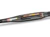
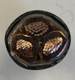
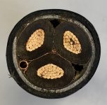
However during the construction, the E.C. found the old existing 2.4KV three -conductor MV cable is lead sheath cable that may be installed in 1949! They have no knowledge of the lead cable such as type and size and don't know what splice kit to use.

I research online and can not find a US manufacture that produce lead sheath MV cable. I only find some manufactures in China, Saudi Arabia still produce the lead sheath cable.

Do you have any knowledge, experience, information that can share regarding the lead sheath MV cable and the splicing kit? Thank you all!
 
Here is a picture of an existing splice into the lead cable for an existing building. We trace the lead cable for hundreds feet. There is no identification/marking on the cable at all. 1678982819022.png
 
I know that there were kits to splice the lead sheathed cable to standard cables. We did a project where we spliced some oil filled single conductor 5 kV cable to standard 5 kV cable and needed to get a compression crimp with a seal to prevent the migration of the oil out of the lead cable.

I also worked on one installation in the mid 70s where we installed some 3 conductor, 750 kcmil, 15 kV, lead sheathed oil filled cables...as I recall it weighed about 12 pounds per foot.
WOW... Do you know what type the oil filled single conductor is? We observed something like a oil leakage at a splice that joints two lead cables on site. The splice is in a junction box and has similar appearance as the below picture (the below picture is a splice of PILC cables which I found online). But the splice we observed is shorter and bigger diameter, and have some oil on the surface...

1678995012218.png
 
Typically, when using a transition splice between PILC cable to EPR, the splice kit will have oil blocks as part of the splice kit to prevent the mineral oil in the paper from migrating out. First pic shows a 3/C PILC cable. The lead sheath is dead ended at the transition splice, but if you look closely, you will see that each conductor is shielded and the shield will need to be made continuous with the spliced cable. We use the transition splices in limited instances on 15kV or less rated cables where we haven't been able to replace an existing PILC cable with EPR, or when we haven't been able to find qualified PILC splicers.

Our 22kV PILC cables are gas-filled PILC cables and we haven't found transition splices that allow us to splice to EPR and also handle the gas tubes in the cable. In that case we have to splice GF-PILC to GF-PILC cable, which is not a cheap repair, or start replacing our PILC cables with EPR. the second pic is a cross section of 22kV GF-PILC cable
 

Attachments

  • 8kV, 3-Cond PILC cable.jpeg
    8kV, 3-Cond PILC cable.jpeg
    128.9 KB · Views: 3
  • 22kV, 3-Cond GF-PILC cable.jpeg
    22kV, 3-Cond GF-PILC cable.jpeg
    144.7 KB · Views: 2
Last edited:
WOW... Do you know what type the oil filled single conductor is? We observed something like a oil leakage at a splice that joints two lead cables on site. The splice is in a junction box and has similar appearance as the below picture (the below picture is a splice of PILC cables which I found online). But the splice we observed is shorter and bigger diameter, and have some oil on the surface...

View attachment 2564449
It is my understanding that the oil is part of the insulation. oil/paper high voltage cable
Note there are also oil cooled high voltage cables where oil is circulated to get rid of excessive heat. An engineer friend of mine designed some of the oil cooling systems used for 138 kV underground distribution in Chicago.
That's correct. Regardless of whether it's PILC or gas-filled PILC, mineral oil is part of the insulation system. For gas-filled-PILC, full insulation rating is achieved when the oil-impregnated, paper insulated cable is pressurized by nitrogen gas, usually at 15 psi, but I have seen lower pressures used.

We also have pipe type underground 115kV feeders that are filled with oil at 200 psi or nitrogen at 200 psi. The oil filled pipe type feeder is 3 miles long serving our remote 115kV substation, and the gas filled pipe type feeder is a 1/2 mile long and powers our 100MW wind tunnel drive motor.
 
I found another thread by ehvmark discussing the oil insulated cable. It provides some helpful information.


Oil filled cable also called "hollow core cable" or "Pirelli cable" has as the name implies a hollow conductor used as a fluid supply channel to pressurize the cable. These cables have been used in the US at 35kV and above but are used a lot overseas possibly as low as 15kV and up to 230kV for bulk power transmission. These operate at pressures ranging from 15 to 200 psi.

PILC or "Paper Lead Cable", (also called "solid cable"), is an oil impregnated paper insulation that has an outer jacket of lead and usually some plastic over that, on the newer ones anyway. There is no pressurizing source for the oil so it operates at atmospheric pressure. This type has been used all over the world at 5 to 35kV since shortly after Thomas Edison did his thing. I have seen samples from as early as around 1910.

Terminating and splicing PILC usually requires solder wiping the accessory to the lead jacket of the cable to form the outer seal. While terminating and splicing EPR is done by hand taping, heat shrinking or cold shrinking (zipper) methods.

You can join EPR to PILC by building a suitable oil barrier on the PILC cable end, so the oil doesn't bleed into the EPR. There are special splice kits available for this. Our you can build two terminals and attach them through a bus. Depends if you are in a manhole, ditch or on a pole.
 
Status
Not open for further replies.
Top