At what amperage is a breaker designed to trip at?

Status
Not open for further replies.

ritelec

Senior Member
Location
Jersey
Just thinking....
I can put up to 100% on a circuit of none continuous load.

On a 20 amp circuit.. If I have several loads equaling 20 amp or one load equalling 20 amps, when will the breaker trip? At 20.000000000000000000001 for an extended period of time?

Does anyone really load a breaker to 100% knowing a true 100% will be drawn ( not even considering maybe there's a slight variable in the equipment to draw little more ???)

Just wondering..
Thanks
 
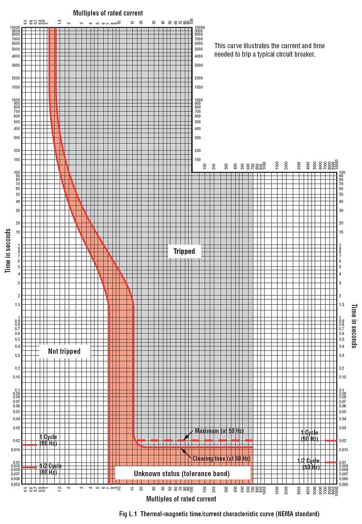
The average breaker is designed as an 'inverse-time' breaker. Meaning, it may take hours or even days for a 20a breaker running at 21 or 22 amps to trip, but seconds when there's 50 or 60 amps coursing through it.

Most breakers have a trip curve chart available from the manufacturer to give you an idea roughly how long it will take to trip the breaker.

TripCurve.jpg
 
That helps...... thank you... Not sure if I would intentionally load to 100% knowing it would see that 100%....

Thanks, appreciate it
 
An actual thermal magnetic breaker does not trip on current anyway. It's very reliably trips when they trip element reaches a certain temperature. As an experiment you can make a breaker trip with almost no current if you heat it up with a hair dryer. You can also make it not trip by turning a fan on it. I have used the fan trick several times when I've had to run tests out in our shop and the only circuit I have is like a 30 amp breaker and I need 40 amps to run for 2 or 3 hours. There's a good chance it would trip eventually at those current levels without some kind of external Cooling. I've been known to do the same thing with power Transformers. It's amazing how much cooler they get with just a little bit of air circulation.
 
the bottom left not tripped rate is interesting

The worst that you could do in the not trip zone is put 7x the rated current through a breaker for 1.5 seconds. I suppose an appliance on a 20 amp breaker could have an internal fault of 140 amps or so that would clear( become an open circuit) that fast...iow it could blow up before the breaker tripped
 
I recently attended a presentation by Eaton. One of the things they told us was that there are no physical differences between their standard breakers and their 100% rated breakers. The differences are in the enclosure size and the bus size. Both the enclosure and the bus are larger for 100% rated breakers.
Remember when standard breakers are tested they are tested in the open at 40°C and they must carry their rated current forever without tripping under those conditions. The 80% is to account for mutual heating where multiple breakers are installed in a common enclosure.
 
We used to do current injection testing on all our main breakers. Witnessing such testing is quite interesting. My take away was that all new breakers should be tested.......and that I trusted fuses a lot more!
 
I recently attended a presentation by Eaton. One of the things they told us was that there are no physical differences between their standard breakers and their 100% rated breakers. The differences are in the enclosure size and the bus size. Both the enclosure and the bus are larger for 100% rated breakers.

Remember when standard breakers are tested they are tested in the open at 40°C and they must carry their rated current forever without tripping under those conditions. The 80% is to account for mutual heating where multiple breakers are installed in a common enclosure.

So does this mean that in practice at 25C ambient any breaker installed in its own enclosure will function as a 100% rated breaker, even if not listed as such? Or can a basic "enclosed circuit breaker" enclosure for plug-on breakers (e.g. QO2100BNF for Square D QO breakers up to 100A) cause more than an additional 15C in temperature rise?

Are 100% rated breaker required to hold indefinitely at their rated current within their enclosures at 40C ambient? I assume the only reason for upsizing the bus is to reduce one source of heat generation.

Thanks, Wayne
 
Typically the trip curves start at 125% of the handle rating. I forget what UL689 required (brain freeze) but it was a lot high than that. The breaker will trip magnetically (instantly begin unlatching) at around 10x the handle rating, older breakers can be more than 20x.
 
180528-1446 EDT

What happens when you open a switch in air with an inductive load carrying current?

One half cycle at 60 Hz is 8.3 milliseconds. A full cycle is double that. Note that these two times are indicated on the trip time curve.

Once a trip mechanism trips there is some time for an arc between contacts to extinguish, and this time is a function of stored energy. Thus, the possibility of current conduction after the breaker contacts physically start to separate.

About 65 years ago I ran a test on a QO to see what times might occur. The load was a very low resistance. Source was 4 or so 6 V car batteries. Peak current approached 6,000 A. I believe tripping mechanism time was possibly 1 to 2 milliseconds from initiation of current, actual closure of a mercury contact, to when contacts started to open. Can't find the notes at this time. Separately I found my measurement on how long it took for the QO contacts to open. The distance is about 1/2 inch and the travel time from just separating to fully open was 4 milliseconds.

There should be no surprise that it takes time from when an overload occurs until the time of no current.

.
 
wonder where motor start up current is on that chart.... how long is that "in rush"?
See how wide the "tolerance band" is during the first cycle? That is also when inrush to a motor will be highest. Motor current rapidly drops - even if mechanically stalled, that initial inrush will be higher then steady locked rotor will be.
 
180528-1711 EDT

kwired:

Can you provide some plots of very high motor inrush current compared to starting current.

Compared to transformers motors have a large air gap in the magnetic path, and also I expect residual flux is near zero as a result of the gradual slow down at turn off.

.
 
180528-1711 EDT

kwired:

Can you provide some plots of very high motor inrush current compared to starting current.

Compared to transformers motors have a large air gap in the magnetic path, and also I expect residual flux is near zero as a result of the gradual slow down at turn off.

.
No but I can tell you in many cases if you get past the first few cycles you are likely tripping on thermal trip instead of magnetic trip. That initial surge of current is often more then what steady locked rotor current is.
 
Oh boy, here we go.

Some would claim a motor’s in rush/starting current is greater than locked rotor amps due to need to establish back EMF. This isn’t a point I’d want to be forced to prove. In fact I’d wager in field measurements would disprove it, assuming a perfectly fine motor starts in close to a no load condition.
 
180528-2026 EDT

kwired:

At
http://forums.mikeholt.com/showthread.php?t=174880&highlight=amperage+inrush
is a thread I started on motor inrush current being non-existent, but rather there is a starting current that is larger than normal running current. The plots I showed had no observable inrush current.

Inrush current dominantly lasts only about 1/2 to 1 cycle, and is usually very large compared to steady state current. Motor starting current typically lasts for a large number of cycles, and is not as huge relative running current.

If you remember you responded in said thread.

I know that there are many that want to call motor starting current inrush current, but motor starting current is so different in its character from other initial currents that it confuses peoples understanding of what is happening in a circuit when the term inrush current is substituted for motor starting current.

If you don't understand how different components and circuits work, then you are not in a good position to design circuits or troubleshoot problems.

.
 
You can also make it not trip by turning a fan on it. I have used the fan trick several times when I've had to run tests out in our shop and the only circuit I have is like a 30 amp breaker and I need 40 amps to run for 2 or 3 hours. There's a good chance it would trip eventually at those current levels without some kind of external Cooling. I've been known to do the same thing with power Transformers. It's amazing how much cooler they get with just a little bit of air circulation.

One of the more hack things I have done: I was doing some work in place that grew plants inside. It was HOT! They were having trouble with a few breakers tripping, even though they were only loaded about 80%. They needed a solution for a day or two till they could get this other AC online or something. There was some bamboo there that they used as stakes to tie the plants to. I made some 1/2" "washers" out of the bamboo and put them between the cabinet and cover to make an air space, and pointed a few fans at it. :cool:
 
An actual thermal magnetic breaker does not trip on current anyway. It's very reliably trips when they trip element reaches a certain temperature. As an experiment you can make a breaker trip with almost no current if you heat it up with a hair dryer. You can also make it not trip by turning a fan on it. I have used the fan trick several times when I've had to run tests out in our shop and the only circuit I have is like a 30 amp breaker and I need 40 amps to run for 2 or 3 hours. There's a good chance it would trip eventually at those current levels without some kind of external Cooling. I've been known to do the same thing with power Transformers. It's amazing how much cooler they get with just a little bit of air circulation.


I’ve been to a house or two where the fan was pointed at the panel with the cover off. Worked for them as well.
 
Status
Not open for further replies.
Top