mbrooke
Batteries Included
- Location
- United States
- Occupation
- Technician
How are you sensing utility loss to start the first generator, and subsequent generator(s)? You will not be able to use the transfer switches unless the first generator is a prime mover. You will need some sort of signal to start the process. I’m assuming the emergency loads are only energized during a power outage?Two redundant generators, the 3rd is a plug box for a mobile unit. No utility feed on the emergency section of the switch gear.
Thats what I'm thinking start both and stagger the transfer time.
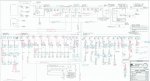
Looked at your one line again, and I see what’s being done. The start control would require paralleling or series the other three transferswitches start contacts to control a three pole contactor. Series if using a N/C contactor, parallel if using N/O. (Assuming the portable has remote start function)
How are you sensing utility loss to start the first generator, and subsequent generator(s)? You will not be able to use the transfer switches unless the first generator is a prime mover. You will need some sort of signal to start the process. I’m assuming the emergency loads are only energized during a power outage?
Sorry, looks like four ATS on load side, hard to see on iPhone!
On the load side of the emergency gear? Can’t be on the line side of the emergency gear, or the generator would never shut off. All of the load side ATS’s canThe first ATS down stream calls for an engine start.
not those, but the load side transferswitches. They will have to control the generator start. The generator will never shut down if you control it from those. All those switches will do is decide on the available source to use. Voltage sense will be dead on both inputs, which will make the switch call for the second source, this starting the generator. Those start contacts should not be connected.3 ATS in series. The first one calls for engine start, the second one upstream is for a mobile genset (normally disabled) and the first one upstream selects between either permanently mounted generator.
The 3 ATSs on the left side are standard utility / Gen ATSs. When any of the three of them they lose power, they will signal the Gen / Gen ATS (on the far right side) to start the primary generator (you will need to bring external control power to that style ATS since they are normally de-energized) and the Gen/Gen ATS would be satisfied and then satisfy the Utility/Gen ATSs, if after a timeout (in the gen/Gen ATS) if the primary generator doesn't start, the alternate generator starts and the Gen/Gen ATS would be satisfied and then satisfy the Utility/Gen ATSs, if after a timeout (in the 2nd Gen/Gen ATS from the right) if the primary generator and secondary generator doesn't start, then the portable generator would be signaled if there was an auto-start capability present and the 2nd Gen/Gen ATS from the right would be satisfied and then satisfy the Utility/Gen ATSs.
The oneline is too blurry to see how the N-G bonding is happening, but if it is occurring at the utility and gens, and no neutrals are brought downstream to any ATS's, and the normally de-energized equipment is in a temperature controlled environment so it doesn't corrode due to condensation, then it seems like a reliable system. Signage would make it easier for the operations staff, but it should get the job doneWould you change this design or keep as is?
The oneline is too blurry to see how the N-G bonding is happening, but if it is occurring at the utility and gens, and no neutrals are brought downstream to any ATS's, and the normally de-energized equipment is in a temperature controlled environment so it doesn't corrode due to condensation, then it seems like a reliable system. Signage would make it easier for the operations staff, but it should get the job done
If at all possible, if it were a 480V system, I would leave the neutrals at their source, bond the N-G at each source so it were solidly grounded, and use 3 pole ATSs, then add transformers as needed downstream to derive 480/277V or step down to 120/208V.Which leads me to ask, how would you ground / bond all this? 3 or 4 pole ATS?
If at all possible, if it were a 480V system, I would leave the neutrals at their source, bond the N-G at each source so it were solidly grounded, and use 3 pole ATSs, then add transformers as needed downstream to derive 480/277V or step down to 120/208V.