Best conduit choice for well house.

4x4dually

Senior Member
Location
Stillwater, OK
Occupation
Electrical Engineer/ Ex-Electrician
As some have seen me post, my friends property burned a while back in the wildfires we had in OK. The well house guys are coming next week to set a new one and I need to feed a 30A service out to it. Seeing how everything before was ran in PVC....thus....burned to complete hell....is there an option that's better? I could run EMT but it's not good for underground and required DB fittings and wrap. I don't have a threader to run rigid. Would it be feasible and/or permissible to run PVC underground and transition to EMT right at ground level using a female pvc adapter and using compression EMT fittings?

Any advice would be much appreciated.

Pics for reference. I also have to come up with a new feed-thru type breaker panel like this. Pole feeds the panel, house is fed-thru, and breakers to cut in barn and pump house feed. I've never seen a panel like this before....not that I claim to have seen it all, but it kinda was like...wow, look at that.
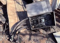
 

Attachments

  • Screenshot 2025-04-17 131330.jpg
    Screenshot 2025-04-17 131330.jpg
    540.3 KB · Views: 31
Yes, you can convert to EMT at ground level, but I would think the heat would still wick to the PVC connection. If you are really trying to avoid this, you could easily form up a curb, and pour a bag or two of concrete to encase 3.5" of the EMT to keep the high heat away from the PVC.
 
PVC transition to a rigid nipple in the ground and then EMT? Or run rigid in the ground and use threadless fittings? Or buy a power threader from Harbor Freight?
 
Maybe I'm over thinking trying to save it the next time the place burns and maybe that's over the top. I guess if the buildings all burn up, it really doesn't matter if the electrical is standing or not.

However, I do have to deal with what's there now and get them powered back up. Lot's of options. He just had his second mechanical heart valve put in so he can't help. This is our families way of helping them out is doing all the electrical for them and covering as much cost as we can.

What sucks is I now have to dig down and try to patch on some new PVC to get the feeds back covered. I have them split nutted together right now just to get the house power on since Lowes was the only thing open and they can't even spell Polaris connector. Not how I would ever like to leave a place, but when he's got heart failure and a kid...they kind of need power. Wire and insulation were actually in great condition it just melted the PVC down around it. We broke all the plastic off and they looked decent. Another issue, they probably won't be long enough to terminate a new panel at a decent height off the ground and I dang sure don't want to re-pull the 4/0 feeds from the pole and to the house. May have to put a junction box under the new panel and Polaris on some extensions. Damn I hate to jerry-rig a new install.

Screenshot 2025-04-17 143206.jpg
 
Maybe I'm over thinking trying to save it the next time the place burns and maybe that's over the top. I guess if the buildings all burn up, it really doesn't matter if the electrical is standing or not.

However, I do have to deal with what's there now and get them powered back up. Lot's of options. He just had his second mechanical heart valve put in so he can't help. This is our families way of helping them out is doing all the electrical for them and covering as much cost as we can.

What sucks is I now have to dig down and try to patch on some new PVC to get the feeds back covered. I have them split nutted together right now just to get the house power on since Lowes was the only thing open and they can't even spell Polaris connector. Not how I would ever like to leave a place, but when he's got heart failure and a kid...they kind of need power. Wire and insulation were actually in great condition it just melted the PVC down around it. We broke all the plastic off and they looked decent. Another issue, they probably won't be long enough to terminate a new panel at a decent height off the ground and I dang sure don't want to re-pull the 4/0 feeds from the pole and to the house. May have to put a junction box under the new panel and Polaris on some extensions. Damn I hate to jerry-rig a new install.

View attachment 2576893
I worked in wildland fire suppression for 6 nine month long fire seasons. I've seen a lot of structures that burned and a lot that didn't. The biggest factor was often the amount of fuel clearance around the structure. If you have 50 feet of clearance from a non combustible structure it will often survive on its own. That means 50 feet cleared of anything that will burn down to bare mineral earth.

The outside covering should be something like Cement Board.
cement board siding.jpg
The frame should be steel studs and channel.
Steel-Stud-Framing-Render_800x500.jpg
The roof should be corrugated iron.

Insulate with non combustible material.

No wood use at all. Stand up a construction strut rack to mount the panel on.
strut C channel.jpg
The panel may need to be marked as "Suitable for Use As Service Equipment" if you run a separate set of service conductors for just the well. See below.

You could construct a well pit which is deep enough to hold the pressure tanks as well as the electrical equipment. You would have to heat teh well house or well pit to a minimum of 40 degrees Fahrenheit.

Another possibility is to call around to concrete box and tank makers and see if they have any damaged drain boxes, cisterns, or septic tanks cheap. If the top of a well vault is below the frost line no heating is necessary. It may take a larger excavator to dig that deep. You can also make a vault out of concrete block. and roof it with a poured on site reinforced concrete slab. You'd need a hole above the well head to pull the pump for maintenance and a man hole with a ladder for access. The man hole opening would have to be large enough to change out the largest piece of equipment in the vault.

There is a specific rule for the electrical supply to water wells that would be used for firefighting. The Service Disconnect for the well power does not have to be grouped with the remainder of the Service Disconnects for the rest of the property. If the electrical utility will supply double terminals on the load side of the meter socket then you run a separate set of service conductors to the well power Service Disconnect. allow enough ampacity for the pump, a light, convenience receptacle, and a heater if you'll need one.

With both the well pit and a vault you must be able to have a gravity drain from the floor to a discharge on lower ground. Without a gravity drain it will flood. The outlet must be screened to prevent animals from using it as a den.

Well vaults make great severe weather shelters. You just install precast stairs instead of a manhole and make sure there is enough space for the whole family to sit down to wait out the storm.

I don't know if you have the time or the money for any of that. They're just ideas.

Good Luck.
 
Even with metallic conduit the conductor insulation is going to bond it's self to the conduit interior wall if it gets hot enough & then cools.
 
Maybe I'm over thinking trying to save it the next time the place burns and maybe that's over the top. I guess if the buildings all burn up, it really doesn't matter if the electrical is standing or not.

However, I do have to deal with what's there now and get them powered back up. Lot's of options. He just had his second mechanical heart valve put in so he can't help. This is our families way of helping them out is doing all the electrical for them and covering as much cost as we can.

What sucks is I now have to dig down and try to patch on some new PVC to get the feeds back covered. I have them split nutted together right now just to get the house power on since Lowes was the only thing open and they can't even spell Polaris connector. Not how I would ever like to leave a place, but when he's got heart failure and a kid...they kind of need power. Wire and insulation were actually in great condition it just melted the PVC down around it. We broke all the plastic off and they looked decent. Another issue, they probably won't be long enough to terminate a new panel at a decent height off the ground and I dang sure don't want to re-pull the 4/0 feeds from the pole and to the house. May have to put a junction box under the new panel and Polaris on some extensions. Damn I hate to jerry-rig a new install.

View attachment 2576893
What about using a Quazite box to connect the existing to the new? You could start 3-5 feet from the structure and be good.
 
What about using a Quazite box to connect the existing to the new? You could start 3-5 feet from the structure and be good.
Ya, that thought had crossed my mind but I'll probably end up putting an outdoor J-box a few feet above ground then feed out the top into the new panel. I can splice a few extra feet on the main feeders in the j-box with crimps. The fire got the loops on the feeders inside the original panel. I don't have enough to go to the top of a new panel and loop back down into the top set of lugs.
 
I just went PVC. Had to extend all the wires since the fire burned off too much of almost all of them to reach a new panel. Not exactly 4' to the bottom of the panel....but who's measurin', right? ;) I wish the Eaton panel had more than 1 large diameter knockout in the bottom. From what I remember, line and load should not be in the same chase, correct? Good thing it is 19 mile away from civilization and no one will see it. I'll plea the 5th. The EGC and bonding are completely hosed in this installation. It's 2/0-2/0-2/0 Cu from here to the meter with a #4 insulated ECG. From here to the panel in the house it's 4/0-4/0-2/0 with no EGC. Since this would be the first means of disconnect, it should be bonded here and the house panel treated as a sub but there's no EGC between the two. I just installed it exactly like it was before since I'm not re-pulling the feeders.

This brings me to a question. The POCO provides a meter base / main breaker combo so "technically", the breaker at the pole is the first means of disconnect, so, that means the EGC should be separate all the way to the pole and bonded at the pole? Is that a correct statement? In that case, these feed-thru lug type panels shouldn't even be used here since this a particular one has no means to float the neutral bar. It's a "main disconnect" only device.

So many things made my eyes twitch but telling myself "just replace what's here and move on" was all I could tell myself. Since I was footing the bill as my donation to the family for their loss, I can't afford to replace it all and make it correct. At least all the dinosaurs in here will be pleased to see the Noalox and tooth brush to work it in despite Holt's preaching it's not needed. LOL

Screenshot 2025-04-25 114052.jpg
 
I worked in wildland fire suppression for 6 nine month long fire seasons. I've seen a lot of structures that burned and a lot that didn't. The biggest factor was often the amount of fuel clearance around the structure. If you have 50 feet of clearance from a non combustible structure it will often survive on its own. That means 50 feet cleared of anything that will burn down to bare mineral earth.

The outside covering should be something like Cement Board.
View attachment 2576899
The frame should be steel studs and channel.
View attachment 2576898
The roof should be corrugated iron.

Insulate with non combustible material.

No wood use at all. Stand up a construction strut rack to mount the panel on.
View attachment 2576896
The panel may need to be marked as "Suitable for Use As Service Equipment" if you run a separate set of service conductors for just the well. See below.

You could construct a well pit which is deep enough to hold the pressure tanks as well as the electrical equipment. You would have to heat teh well house or well pit to a minimum of 40 degrees Fahrenheit.

Another possibility is to call around to concrete box and tank makers and see if they have any damaged drain boxes, cisterns, or septic tanks cheap. If the top of a well vault is below the frost line no heating is necessary. It may take a larger excavator to dig that deep. You can also make a vault out of concrete block. and roof it with a poured on site reinforced concrete slab. You'd need a hole above the well head to pull the pump for maintenance and a man hole with a ladder for access. The man hole opening would have to be large enough to change out the largest piece of equipment in the vault.

There is a specific rule for the electrical supply to water wells that would be used for firefighting. The Service Disconnect for the well power does not have to be grouped with the remainder of the Service Disconnects for the rest of the property. If the electrical utility will supply double terminals on the load side of the meter socket then you run a separate set of service conductors to the well power Service Disconnect. allow enough ampacity for the pump, a light, convenience receptacle, and a heater if you'll need one.

With both the well pit and a vault you must be able to have a gravity drain from the floor to a discharge on lower ground. Without a gravity drain it will flood. The outlet must be screened to prevent animals from using it as a den.

Well vaults make great severe weather shelters. You just install precast stairs instead of a manhole and make sure there is enough space for the whole family to sit down to wait out the storm.

I don't know if you have the time or the money for any of that. They're just ideas.

Good Luck.
Excellent ideas
 
Excellent ideas
Indeed. Great info. I provided a 1" PVC stubbed up with wire hanging out and the well contractor is going to do the rest. I can almost guarantee it will be a wooden structure and not comply with ANY of those recommendations if I was guessing. I think they just pre-build boxes and set them on a slab or on the ground and go. I stayed out of that lane. Didn't want pulled into more obligations.
 
Not exactly 4' to the bottom of the panel....but who's measurin', right?

There is no height requirement per NEC. POCO might have one.

From what I remember, line and load should not be in the same chase, correct?
If you're talking about the service conductors not being in the same conduit as the feeders, you are correct.

The EGC and bonding are completely hosed in this installation
Don't you mean GEC?
 
There is no height requirement per NEC. POCO might have one.

Opps. Not sure why I thought that. I see there is just a max height for the operating handles.

If you're talking about the service conductors not being in the same conduit as the feeders, you are correct.

Yes. Please excuse my lack of proper jargon.

Don't you mean GEC?

Both actually. If the conductors coming out of the 200A breaker that's under the meter on the POCO pole, then the "service conductors" are going from the pole to this panel. Since this panel has a 200A main breaker, then it would be the first means of disconnect so I'd believe the GEC should be located at this panel. It is not. And even it it was, there is already a GEC under the house panel. House panel is bonded. There is also no EGC between the house panel and this disconnect to route EGC and neutral separately. We'd get into the multiple GEC situation that I've seen numerous Holt videos against. The entire install is kinda "novice" and I don't really like how it's setup.
 
Oops. Not sure why I thought that. I see there is just a max height for the operating handles.

Yes. Please excuse my lack of proper jargon.

Both actually. If the conductors coming out of the 200A breaker that's under the meter on the POCO pole, then the "service conductors" are going from the pole to this panel. Since this panel has a 200A main breaker, then it would be the first means of disconnect so I'd believe the GEC should be located at this panel. It is not. And even it it was, there is already a GEC under the house panel. House panel is bonded. There is also no EGC between the house panel and this disconnect to route EGC and neutral separately. We'd get into the multiple GEC situation that I've seen numerous Holt videos against. The entire install is kinda "novice" and I don't really like how it's setup.
If this service is built under the 2020 or 2023 editions of the National Electric Code (NEC) then that Enclosed Breaker can be treated as an Emergency Disconnect which is not the Service Disconnect and have a main bonding jumper installed, because the Grounded Conductor of the Service conductors from the Service Point to the Service Disconnect must be bonded to all Service conductor enclosures. You would not have to install a Grounding Electrode System nor connect any existing Grounding Electrodes to the Emergency Disconnect since it is not Service Equipment in this case It also does not have to be have an Equipment Grounding Conductor run from it to the panel in the house.

If it is under the 2017 or earlier version of the NEC then you will have to wire it as a service disconnect as described below. Using it as an Emergency Disconnect would be far less work and less expensive in terms of additional parts.

If you decide to have any additional breakers in that enclosure at the meter, for any purpose, it will have to be wired as the Service Disconnect with a Grounding Electrode System connected to it by a Grounding Electrode Conductor sized for the size of the Service. The Main bonding jumper would remain in place. You then have to rewire the house panel as a feeder supplied main distribution panel by separating all of the EGCs onto add on EGC busbars mounted directly to the panel enclosure metal, making sure that all of the Grounded Conductors (Neutrals) are connected to the same busbar as the Grounded Conductor (Neutral) of the Feeder, and you would have to terminate the newly installed EGC from the enclosed breaker Service Disconnect Grounded Conductor busbar to a compliant Grounding Electrode System. The add on EGC busbars would have to be made by the original manufacturer of the panel and be one of the part numbers listed on the panel's labeling. Using a different manufacturers busbars or a model that is not shown on the panels labeling can cause you to fail inspection.

Now the conductors to the water well should be Service Conductors that have no disconnect at the meter and Emergency Disconnect locations nor at the enclosed breaker Service Disconnect if you decide to convert it to one. The Service Conductors to the well and be connected to double terminal lugs on the load side of the meter socket. If the utility will not allow double terminal lugs in the meter socket enclosure then you can tap them off of the Service Entry Conductors before they terminate in the Service Disconnect or the Emergency Disconnect depending on which way you wire the enclosed breaker. The underlying principle here is that there should be no way to disconnect the water pumps power except for the Separate Service Disconnect located at the water pump or the well head. That avoids the possibility of the power to the water pump being disconnected while it is in use to suppress a fire. The Code specifically allows the Service Disconnect for the water pump to be located away from the other service disconnects.

230.72 Grouping of Disconnects.
(A) General.
The two to six disconnects, if permitted in 230.71, shall be grouped. Each disconnect shall be marked to indicate the load served.

Exception: One of the two to six service disconnecting means permitted in 230.71, where used only for a water pump also intended to provide fire protection, shall be permitted to be located remote from the other disconnecting means. If remotely installed in accordance with this exception, a plaque shall be posted at the location of the remaining grouped disconnects denoting its location.
Every well I wired up was tied to a branch circuit breaker. Every well I ever worked on was wired to a branch circuit breaker. You are making it sound like the well should be wired up like a fire pump. I don't think you are allowed to do that.
 
Every well I wired up was tied to a branch circuit breaker. Every well I ever worked on was wired to a branch circuit breaker. You are making it sound like the well should be wired up like a fire pump. I don't think you are allowed to do that.
You are correct in saying that this sounds "like the well should be wired up like a fire pump." That is intentional. The exception for a Service Disconnect for a water pump which is also used for fire protection is modeled after the Service arrangement of a dedicated fire pump and for the same reasons.

The arrangement I describe here supplies the well through a branch circuit breaker. The separate Service Conductors supplied directly off the load side of the meter socket, or from the service entry conductors on the load side of the meter, supply the Service Equipment in which that branch circuit breaker is located at the pump or well head.

230.46 Spliced and Tapped Conductors.
Service-entrance conductors shall be permitted to be spliced or tapped in accordance with 110.14, 300.5(E), 300.13, and 300.15. Power distribution blocks, pressure connectors, and devices for splices and taps shall be listed. Power distribution blocks installed on service conductors shall be marked “suitable for use on the line side of the service equipment” or equivalent. Pressure connectors and devices for splices and taps installed on service conductors shall be marked “suitable for use on the line side of the service equipment” or equivalent.


Those Service Conductor Taps supply the Service Equipment in which that branch circuit breaker for the well pump is located. The tapped set of Service Conductors is commonly used to supply a small panel located at the water pump or the well head with a 30 or 60 ampere Main Breaker which is also the Service Disconnect.

230.72 Grouping of Disconnects.
(A) General.
The two to six disconnects, if permitted in 230.71, shall be grouped. Each disconnect shall be marked to indicate the load served.

Exception: One of the two to six service disconnecting means permitted in 230.71, where used only for a water pump also intended to provide fire protection, shall be permitted to be located remote from the other disconnecting means. If remotely installed in accordance with this exception, a plaque shall be posted at the location of the remaining grouped disconnects denoting its location.


Branch Circuit Breakers for the pump, needed lighting, a servicing receptacle outlet, and any needed heating are located in the well panel. It's exactly like having up to 6 Service Disconnects to make up one set of Service Equipment except that one of those Service Disconnects is not Grouped with the other/s. The US National Electric Code (NEC) specifically allows the Service Disconnect for a well that is also used for fire protection to be located remotely from the other Service Disconnect/s.

Again this is to make sure that the power to the water pump cannot be disconnected accidentally when other Service Disconnects are being opened to shut off the power to the building were the fire is. It isn't that strange if you think about it.
 
The well house is fed from a breaker in the new panel. It is in no way intended for use as fire suppression. In fact, it was tried to be used as one and you can see how it worked out.
 
Top