Bonding antenna and coaxial cable.

Status
Not open for further replies.
This is a topic that I do not fully understand, but of great interest to me since I got my amateur ticket last year.

Antenna grounding serves several different purposes, including getting best signal, safety for static discharge, and lightning protection.

You can pretty much strike lightning protection from this discussion. There is some black art there which I would not trust to anyone except a lightning protection professional. NEC minimum requirements do not address lightning protection for antennas. That #10 for grounding the antenna is not even close to what is needed for a lightning down conductor.

Other than static pickup, I don't believe that grounding will make a difference to the signal quality for the antennas you are considering. According to the supplier's site, these antennas have a 300 ohm balanced output (think 'twin lead') without grounded elements connected to the feedline. If you switch to coax, you will do so at a 'balun' and the grounded shield will only run from the balun on down.

For static discharge, I don't believe that adding a ground rod will make a difference; simply connect the #10 to the intersystem bonding terminal.

If lightning does strike your installation, using the #10 and not adding additional grounding, you can expect major damage. As I said, this is NEC minimum and _not_ lightning protection. If you want a system where lightning can strike the antenna with a high likelihood of only minimal damage (say just to the strike termination point) then IMHO you will need additional ground electrodes, grounding conductors on the order of #2 Cu, and professional design.

As I said: the above is speaking outside of my professional experience, so spice with a large grain of salt.

-Jon

The antenna comes with a matching transformer, which looks like it's bonded to the antenna mast. My Winegard is like that.

33089179_scaled_202x150.jpg


Bad pic, sorry, it's off the manufacturer's site. I don't see a separate terminal to ground the mast in order to comply with NEC 810.21, but it may be there if the twin lead is used.
 
Actually, the one pictured is probably 75 ohms to match the impedance of the cable commonly used in television.
I don't think there's actually an impedance-relevant parameter to its design. It's simply a modified Type F barrel coupling. It can be used for either a 50- or 75-ohm antenna system, or most any system which uses Type F connections.
 
I don't think there's actually an impedance-relevant parameter to its design. It's simply a modified Type F barrel coupling. It can be used for either a 50- or 75-ohm antenna system, or most any system which uses Type F connections.

There most certainly is an impedance relevant parameter to its design.

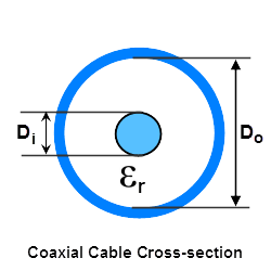
The impedance is determined by the ratio of the outside of the inside conductor to the inside of the outside conductor.
coax2_pic.png


Here is an online calculator:

https://www.pasternack.com/t-calculator-coax-cutoff.aspx

Type F connectors come in both 75 and 50 ohm variants.

For example:


http://www.air802.com/f-male-50-ohm-crimp-connector-rg58-lmr195.html

F connectors are commonly used in CATV 75 ohm applications. However this F male connector is designed for 50 ohm application and is sized for use with RG58 and 195-Series type cables, such as AIR802® CA195 and Times Microwave's LMR195®.
 
There most certainly is an impedance relevant parameter to its design.

The impedance is determined by the ratio of the outside of the inside conductor to the inside of the outside conductor.
coax2_pic.png


Here is an online calculator:

https://www.pasternack.com/t-calculator-coax-cutoff.aspx

Type F connectors come in both 75 and 50 ohm variants.

For example:


http://www.air802.com/f-male-50-ohm-crimp-connector-rg58-lmr195.html
I was talking about the grounding block in particular. Not any and every component of a coaxial antenna system.

I am also aware there are some "snake oil" salespeople out there that'll use any reason, many even based on an off-shoot of fact, to sell their product. Truth be told, given adequate dielectric and distance between conductive parts, that design grounding block contributes no significant change to an antenna system's impedance.
Any "lump" change in impedance along a transmission line, like a mismatched ground block, will cause reflections and standing waves along the transmission line.
In this case, since the impedance change extends over a very short distance the effects will be minimal as long as the wavelength (in cable) of the frequency range in question is large compared to the length of the grounding block. (Basically the reflection from the far end of the block cancels the reflection from the near end.)
At a frequency of 3GHz (the upper design range of the block) its length is NOT small compared to the wavelength and the effects could be severe. At broadcast TV frequencies, not so much.
It all depends on what signal frequencies you are dealing with.
 
I was talking about the grounding block in particular. Not any and every component of a coaxial antenna system.

I am also aware there are some "snake oil" salespeople out there that'll use any reason, many even based on an off-shoot of fact, to sell their product. Truth be told, given adequate dielectric and distance between conductive parts, that design grounding block contributes no significant change to an antenna system's impedance.

The grounding block follows the same laws of physics as any part of the transmission line system. The grounding block I showed should present no significant change because it is a 75 ohm connector. If you spend more than a couple dollars on a grounding block, the impedance will be part of the specs. If, for some reason, a 50 ohm connector got stuck there, we would see an 'impedance bump' where some of the signal would be reflected back into the antenna and appear to be a product of a lossy connection. Such a mismatch can cause a connection that was normally .2 dB to go over 1dB at frequencies higher than 400 mhz.

The OP is dealing with some very weak signals and any loss will be noticeable. I know, I have an OTA system as my primary TV set up. The best method is to use a mast mounted pre-amp ahead of the coax and use low loss coax and matched impedance connectors and blocks. The difference of 1 dB can mean getting a digital signal with full clarity vs. a scrambled up mess.

F type connectors that are 50 ohms are used for low (100 watts or so) power two way radio installations. They are not popular, but some people use them. They won't fit properly on 75 ohm cable.

It's also permissible to forgo the block altogether and use a different method. This is done by stripping back some cable and using a hose clamp to secure a conductor to the shield. That would eliminate the loss of the block and the two extra connectors. A total of about 1/2 dB. I don't like that method at all.

Nothing I am talking about is snake oil. It's just plain physics. I use a 50 year old Winegard with a broken element. The rest of the system is important. A mast mounted pre-amp, a rotator, good, low loss coax and good waterproof F connectors. One of the stations I can get to the north of me is 72 miles. My antenna is about 30 feet above ground level. Any compromise in matching or transmission line quality will most definitely affect fringe channels. I get around 40 channels, 20 or so of which are not dupes. That didn't happen by accident.
 
Any "lump" change in impedance along a transmission line, like a mismatched ground block, will cause reflections and standing waves along the transmission line.
In this case, since the impedance change extends over a very short distance the effects will be minimal as long as the wavelength (in cable) of the frequency range in question is large compared to the length of the grounding block. (Basically the reflection from the far end of the block cancels the reflection from the near end.)
At a frequency of 3GHz (the upper design range of the block) its length is NOT small compared to the wavelength and the effects could be severe. At broadcast TV frequencies, not so much.
It all depends on what signal frequencies you are dealing with.

OTA goes up to 890 megs now. Much less wiggle room than the old VHF TV days.
 
OTA goes up to 890 megs now. Much less wiggle room than the old VHF TV days.

Yup, but 1GHz is still a longer wavelength than 3GHz. :)

Note that if the length of the block gets up to 1/4 wavelength the two reflections reinforce rather than cancel. Probably the worst possible case.
If you can stay below 1/16 wavelength you are probably OK.
 
Yup, but 1GHz is still a longer wavelength than 3GHz. :)

Note that if the length of the block gets up to 1/4 wavelength the two reflections reinforce rather than cancel. Probably the worst possible case.
If you can stay below 1/16 wavelength you are probably OK.

I have seen impedance bumps a couple inches long spike the SWR up to over 4:1 on a 146 mhz (2 meter band) system. The bump was caused by the coax being squished in the door and changing its diameter for a couple inches.

I have read studies where 75 ohm N connectors used with 50 ohm systems increased connector loss 5 fold at 440 mhz.

We aren't talking about tons of money to use the correct impedance hardware. Just spend the extra few cents and do it right so you can get the news and weather 3-4 seconds before people using cable or satellite do and watch TV in full 1080 with no crappy artifacts.
 
Yup, but 1GHz is still a longer wavelength than 3GHz. :)

Note that if the length of the block gets up to 1/4 wavelength the two reflections reinforce rather than cancel. Probably the worst possible case.
If you can stay below 1/16 wavelength you are probably OK.
POINT: Exactly what is 1/16 the wavelength at 1GHz?
 
POINT: Exactly what is 1/16 the wavelength at 1GHz?

Without taking into consideration velocity factor, it would be .738125 inches.

If we assume a common dielectric velocity factor of .66, the above figure goes down to .4871 inches.

Edit to add: 1/4 wave, 1000 Mhz, velocity factor of .66 comes out to 1.948 inches. Just about the length of a grounding block conductor.
 
... I get around 40 channels, 20 or so of which are not dupes. That didn't happen by accident.
If you get 40 channels, I bet you live in an area with much flatter terrain than I. I've not experienced all the terrain of MI, but I worked and lodged in the Flint area for about a year in the mid 90's... and it's fairly flat in that part of the state. As a part-time job I installed DTB satellite TV systems. I've seen many a homeowner up there get lots of TV channels from all around the region.
 
Without taking into consideration velocity factor, it would be .738125 inches.

If we assume a common dielectric velocity factor of .66, the above figure goes down to .4871 inches.

Edit to add: 1/4 wave, 1000 Mhz, velocity factor of .66 comes out to 1.948 inches. Just about the length of a grounding block conductor.
The one on the side of my house is 1".
 
If you get 40 channels, I bet you live in an area with much flatter terrain than I. I've not experienced all the terrain of MI, but I worked and lodged in the Flint area for about a year in the mid 90's... and it's fairly flat in that part of the state. As a part-time job I installed DTB satellite TV systems. I've seen many a homeowner up there get lots of TV channels from all around the region.

I am in Western Michigan, about 7 miles from Lake Michigan. I am using the same TV antenna my grandmother used in the 60's. Back then we got three channels, 3, 8 and 13. Channel 9 was around because we could get it at our trailer, 55 miles north of here. The Channel 9 is 72 miles from here. I can get it perfectly with my antenna pointed north.

Since I am so close to the lake, all the stations I get are east of me. Most are south east.

Go to TV Fool and fill in the info, it's pretty accurate.

www.tvfool.com
 
If you get 40 channels, I bet you live in an area with much flatter terrain than I. I've not experienced all the terrain of MI, but I worked and lodged in the Flint area for about a year in the mid 90's... and it's fairly flat in that part of the state. As a part-time job I installed DTB satellite TV systems. I've seen many a homeowner up there get lots of TV channels from all around the region.

For those who are interested in exploring over the air digital TV, there is an excellent signal strength mapping tool available free at http://www.tvfool.com/.
It calculates signal strength using transmitter radiation patterns, terrain mapping and your receiving antenna location and height. It even calculates signal diffraction from ridge lines, etc.
As a bonus it tells you what RF frequency a channel uses instead of just the digital channel number.
And it indicates just what direction to point your receiving antenna. The biggest practical limitation, IMHO, is that it does not take multipath interference into effect.

One friend, for example, found that they got better reception of one channel by pointing their antenna at a large barn higher up the hill which acted as a reflector than they did pointing directly at the station.

Finally, I found that when reception was marginal, I needed to enter the station RF information directly into my TV instead of relying on the automatic scan feature. This is particularly important when using a rotatable antenna for stations in different directions as the auto scan would never see all of the channels with one antenna position setting. (If you have just the right kind of steerable antenna with digital interface, some TVs will actually rotate the antenna during the scan process and store the direction of each signal!)
 
Status
Not open for further replies.
Top