You are using an out of date browser. It may not display this or other websites correctly.
You should upgrade or use an alternative browser.
You should upgrade or use an alternative browser.
BONDING STEP DOWN XFMR
- Thread starter litebx
- Start date
- Location
- New Jersey
- Occupation
- Journeyman Electrician (retired)
Here's a different size XFMR but the concept is the same. In general MIBG's are not required (except for on the GEC) but guys seem to always use them anyway. There should be a ground terminal for all of the connections.
What you should have is connection wise is this with the corresponding table:
Primary EGC-T250.122
Secondary SSBJ-T250.102(C)(1)
SBJ-T250.102(C)(1)
GEC-T250.66

What you should have is connection wise is this with the corresponding table:
Primary EGC-T250.122
Secondary SSBJ-T250.102(C)(1)
SBJ-T250.102(C)(1)
GEC-T250.66
From what I have came across and like to do myself is to install at least a double barrel lug bolted to the XO point.If you have two Nuetrals might be able to install a three barrel lug. Run the grounded conductor ( Nuetral ) and the green bonding wire from that lug. I always use grade 5 hex head cap screws along with flat washers & a lock washer secured using a torque wrench force trouble free connection on lugs.
Dsg319
Senior Member
- Location
- West Virginia
- Occupation
- Wv Master “lectrician”
Why do the primary conductors look larger than the secondary’s? VD compensation or my eyesHere's a different size XFMR but the concept is the same. In general MIBG's are not required (except for on the GEC) but guys seem to always use them anyway. There should be a ground terminal for all of the connections.
What you should have is connection wise is this with the corresponding table:
Primary EGC-T250.122
Secondary SSBJ-T250.102(C)(1)
SBJ-T250.102(C)(1)
GEC-T250.66
View attachment 2578408
- Location
- New Jersey
- Occupation
- Journeyman Electrician (retired)
Neither VD or your eyes unless you consider that they didn't see that the secondary has two sets of parallel conductors.Why do the primary conductors look larger than the secondary’s? VD compensation or my eyes
")
Strathead
Senior Member
- Location
- Ocala, Florida, USA
- Occupation
- Electrician/Estimator/Project Manager/Superintendent
What are you using MIGB to stand for? Type in in to Google and it stands for Malleable insulated ground bushing. I am guessing for you it is some kind of ground bar.GOOD MORNING! I NEED SOME ASSISTANCE. I WANT TO MAKE SURE THAT I AM CONNECTING, GROUNDING, & BONDING THE MIGBs CORRECTLY TO A 225 KVA XFMR. MAYBE A PHOTO IF IT WOULD BE TOO MUCH TO TYPE. THANKS
Sent from my SM-G991U1 using Tapatalk
Respectfully , your question is way too vague. There are many, many ways to accomplish grounding and bonding of the secondary side of a transformer.
Strathead
Senior Member
- Location
- Ocala, Florida, USA
- Occupation
- Electrician/Estimator/Project Manager/Superintendent
Infinity, why would you run your line side EGC to the XO point on the transformer instead of the case of the transformer (IE the ground bar)? IMO that seems like a code violation to me. I get that the electrons will find there way, but they depend on a bolt at the XO bar.Here's a different size XFMR but the concept is the same. In general MIBG's are not required (except for on the GEC) but guys seem to always use them anyway. There should be a ground terminal for all of the connections.
What you should have is connection wise is this with the corresponding table:
Primary EGC-T250.122
Secondary SSBJ-T250.102(C)(1)
SBJ-T250.102(C)(1)
GEC-T250.66
View attachment 2578408
Tulsa Electrician
Senior Member
- Location
- Tulsa
- Occupation
- Electrician
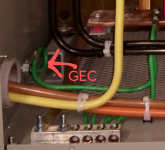
I'm not him, however I don't see that. What I see is the GEC ran to XO. Primary EGC looks like it goes to the bar.
Hope I'm looking at correctlyInfinity, why would you run your line side EGC to the XO point on the transformer instead of the case of the transformer (IE the ground bar)? IMO that seems like a code violation to me. I get that the electrons will find there way, but they depend on a bolt at the XO bar.
Attachments
- Location
- New Jersey
- Occupation
- Journeyman Electrician (retired)
It's not, that's the GEC in a separate raceway (hence the bonding bushing) as Tulsa mentioned.Infinity, why would you run your line side EGC to the XO point on the transformer instead of the case of the transformer (IE the ground bar)? IMO that seems like a code violation to me. I get that the electrons will find there way, but they depend on a bolt at the XO bar
Dsg319
Senior Member
- Location
- West Virginia
- Occupation
- Wv Master “lectrician”
Woo. I’ll count it a blessing those weren’t snakes!!!Neither VD or your eyes unless you consider that they didn't see that the secondary has two sets of parallel conductors.