Can Surge Protective Devices (or the MOVs) work without shunting to ground?

Status
Not open for further replies.
A surge suppressor can do just as good a job at suppressing line to line transients when connected directly from line to line as it can with two devices each connected from one line to ground.
What it cannot do is provide any protection against common mode voltage (an abnormal transient voltage which affects both lines equally with the same polarity.)

To restate that, if the fault or transient condition applied +1000VDC to L1 with respect to ground and -1000VDC to L2, then a suppressor from L1 to L2 will see and excess voltage of 2000VDC and will conduct.
But if it applies +1000VDC to L1 and also +1000VDC to L2 a suppressor from L1 to L2 will not see any abnormal voltage and will provide no protection. In both cases two suppressors from L1 and L2 to ground (not neutral!!) would provide protection.

Another aspect to consider is whether a common mode transient will in fact do any damage to a connected load. The answer to that depends entirely on the details of the load and its insulation. 3

I finally got all your were saying above. You just rewords the concept shared to me by the person who taught me how to select SPDs and I got confused. Lol. About the last part. He only gave example that common mode voltage from surge can affect the chassis. He mentioned how chassis is rated for say 600v. Now a lightning that affect the lines can cause the chassis to be say 5500v. And if the chassis is connected to any transformer, the arc can jump to the transformer secondary (if it's grounded) and destroy the insulation and affect the core, etc. He didn't mention the CCTV, TV load can be affected. So I ignored it and want to save by not using line to ground SPDs. Do you know how many items would be affected? But if the load is not connected to chassis. Then no problem, so we can make the rule that common mode voltage damage on the load can only happen if it is connected to chassis? right? Can you think of exception?
 
It was the manner in which it was expressed.
Water under the bridge,

My questions were quite ignorant for an electrical engineer. I'm not a electrical engineer. Therefore can someone please re phrase the following. I still have a hard time understanding it. I know as resistance increases, current deceases. so by increasing the series impedance or resistance, the MOV current decreases. But what is meant by "this curve the MOV is sitting at the peak of the event". Can someone share illustration of this curve (what curve)? Also V= IR, If V=4800v, and I = 24000A in Golddigger example, then won't R=V/I= 4800V/24000A = 0.2 Ohm. But Golddigger wrote 0.02 Ohm, confusing me further what he was referring to.

Someone kindly rewords this for us who are not electrical engineers. Quoting Golddigger:

"
An MOV does not literally short. It takes on a much smaller impedance than it had just below the threshold voltage.
At any voltage above the threshold, as gar said, it will seriously conduct. Its current versus voltage curve is totally independent of what series resistance is present in the source circuit. What change is at which point along this curve the MOV is sitting at the peak of the event.
If you have a transient fevent4 which is capable of sourcing 24000A into a bolted short on a nominal 120V circuit, and the source of the fault current is at 4800V, the effective internal resistance of that source is .02 Ohm. A 120V design MOV might conduct 24000A at 480V (for example). That gives the MOV an effective internal resistance of .02 Ohm also at 480V.
The MOV might be able to clamp the voltage at its terminals to about 480V. But if the series resistance between the source and the MOV (added wire length, inductance, etc.) is .2 Ohms the maximum current is now roiughly 2400A the MOV will be able to clamp the voltage to much less than 480V. More like, perhaps 300V, which could be below the damage threshold of the protected load. The MOV is now operating at a different point on its unchanged voltage/current curve. "
 
181205-0927 EST

tersh:

See
https://www.vishay.com/docs/29079/varintro.pdf
for a good discussion on varistors. Note that log scales are used on some of the plots.

Resistance is defined as R = V/I for a linear resistance. Linear meaning that when a curve of I vs V for the device is plotted that the plot is a straight line on linear graph paper. This linearity breaks down for any real world device, if for no other reason than heat. However, for many devices in real world applications linear is a good description when operated within rating limits. An Ohmite 10 W power resistor has a relative constant resistance from 0 to full rated power at constant room temperature. Probably within a few percent. I have not run the experiment. A 1500 W space heater shows about a 10% increase in resistance from cold, room temperature, to its heated condition, nichrome at orange color.

A device like a semiconductor diode has a reverse polarity resistance that is very high, just microamperes for a unit rated 1 A in the forward direction. Reverse resistance is non-linear as is the forward resistance also not linear. See
https://www.electronics-tutorials.ws/blog/i-v-characteristic-curves.html
https://www.electronics-tutorials.ws/diode/diode_3.html

For the resistance of a non-linear device, such as a diode, Zener diode, thyrector, or MOV, we have an I-V characteristic curve that can not be described by a simple linear equation. At any point on the curve we can calculate v/i and say that is the resistance because that would be the resistance of a linear resistance at that voltage. But possibly we are more concerned with the slope of the curve which is delta-v/delta-i.

Study the above references and see if that helps.

.

Ok. Thanks I read it. Now something I want to clarify in Golddigger paragraph:

"If you have a transient fevent4 which is capable of sourcing 24000A into a bolted short on a nominal 120V circuit, and the source of the fault current is at 4800V, the effective internal resistance of that source is .02 Ohm. A 120V design MOV might conduct 24000A at 480V (for example). That gives the MOV an effective internal resistance of .02 Ohm also at 480V.
The MOV might be able to clamp the voltage at its terminals to about 480V. But if the series resistance between the source and the MOV (added wire length, inductance, etc.) is .2 Ohms the maximum current is now roiughly 2400A the MOV will be able to clamp the voltage to much less than 480V. More like, perhaps 300V, which could be below the damage threshold of the protected load. The MOV is now operating at a different point on its unchanged voltage/current curve. "

What is fevent4? does he mean event? but why add f and 4? Second.. what is "bolted short".. why use the word "bolted"? Also to correct it.. his R=V/I = 4800v/24000A = 0.2 Ohm instead of 0.02. This is no big deal but for those trying to follow. It may get confusing as one has to absorb the other stuff. And he mentioned "
But if the series resistance between the source and the MOV (added wire length, inductance, etc.) is .2 Ohms the maximum current is now roiughly 2400A." Does he mean 2 Ohm instead of 0.2 Ohm?

In short I think what he is simply saying is that if the outside series resistance is bigger than the MOV internal resistance. Then the current would be lesser than if it were only exposed to the MOV internal resistance, right? How did you understand the paragraph?
 
A surge suppressor can do just as good a job at suppressing line to line transients when connected directly from line to line as it can with two devices each connected from one line to ground.
What it cannot do is provide any protection against common mode voltage (an abnormal transient voltage which affects both lines equally with the same polarity.)

To restate that, if the fault or transient condition applied +1000VDC to L1 with respect to ground and -1000VDC to L2, then a suppressor from L1 to L2 will see and excess voltage of 2000VDC and will conduct.
But if it applies +1000VDC to L1 and also +1000VDC to L2 a suppressor from L1 to L2 will not see any abnormal voltage and will provide no protection. In both cases two suppressors from L1 and L2 to ground (not neutral!!) would provide protection.

Another aspect to consider is whether a common mode transient will in fact do any damage to a connected load. The answer to that depends entirely on the details of the load and its insulation. 3

I haven't used any common mode voltage protection between line to ground before because my equipment doesn't have any metal chassis so I don't worry about the chassis getting high voltage. Can you mentioned any scenario where a load without metal chassis can still be damaged by common mode voltage surge? I couldn't think of any before so I didn't install any line to ground protection for the particular circuits connected to that SPD. But if the load which doesn't feel the potential difference between common mode voltage can still be damaged. Then I'll put the protection as soon as possible even if the loads don't have any chassis.
 
I haven't used any common mode voltage protection between line to ground before because my equipment doesn't have any metal chassis so I don't worry about the chassis getting high voltage. Can you mentioned any scenario where a load without metal chassis can still be damaged by common mode voltage surge? I couldn't think of any before so I didn't install any line to ground protection for the particular circuits connected to that SPD. But if the load which doesn't feel the potential difference between common mode voltage can still be damaged. Then I'll put the protection as soon as possible even if the loads don't have any chassis.
You don't have to be a genius to know that potential differences will find ways to equalize, whichever is higher to a much lower potential! That said, equipment that you have designed to be ungrounded might still get grounded, unintentionally. If what you have is designed for outer space, then don't bother having it protected from surges, IMO.
 
You don't have to be a genius to know that potential differences will find ways to equalize, whichever is higher to a much lower potential! That said, equipment that you have designed to be ungrounded might still get grounded, unintentionally. If what you have is designed for outer space, then don't bother having it protected from surges, IMO.

But don't forget that in common mode voltage surge, there is no potential difference so both line to line is exposed to same voltage. So if your load is line to line, and it's not connected to any ground. Then how could the load get exposed to that surge since there is no potential difference? Try to understand this subtle scenerio. This is why in the world of Surge Protective Devices. Common mode voltage surge is only related to ground. Without ground, the surge may not affect you. I'm asking confirmation from Golddigger if he has exception to this rule. Maybe he agrees with me there is no exception.
 
181205-2231 EST

tersh:

Put a 1.5 V battery out in space. Connect two 1k resistors in series across the battery. One mile away place a copper plate. Connect a 1,000,000 V battery from the resistors center point to the copper plate. Unlikely to be any continuous conductive current, but just after the connection there will be a small capacitive current for a short time.

The battery should not be damaged, and we probably don't care that there is about a 200V/ft gradient in space.

What your structure is and how it is insulated from earth will determine if you have a problem in your example.

.

You mean even for common mode voltage surge where the voltage is exactly equal in both lines where the MOV or load won't detect it because there is no potential difference, the capacitive coupling from somewhere can affect it? But it would still make the voltage equal.

If the above is not it. I don't know what example you were talking about. Kindly explain in direct words. Thanks.
 
191205-2401 EST

tersh:

You have suggested that you have some device that is isolated (insulated) from earth. If the conductive part of that device has a voltage applied to it that is large relative to earth, then whether any or what kind of current flows from the device to earth from the applied common mode voltage is dependent upon voltage, and conductivity of your isolation means. Your dominate conductive means is likely capacitive.

.
 
Any Europeans here or elsewhere using only 240v power system (without 120v)?

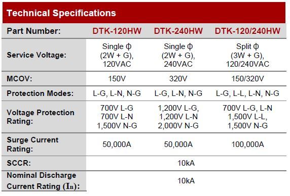
The VPR of 120v SPD are lower (700v in the case of the following or 500v), while the VPR of 120v SPD are 1200v.
dA6IM1.jpg


So for those Europeans (or Middle Easterners or Chinese) using only 240v. Do you use 240v-120v step down transformers to use the lower VPR 120v SPDs, or do you still use 240v SPDs with higher VPR. Why?

If they use step down transformer to take advantage of 120v SPD, then the VPR would be lower and offer greater protection to the load, right? How many of them do this in practice? What do you think guys? Any disadvantage of using step down transformer and 120v SPD combo?
 
Actually, the most common method of step down transformer that is used here would more commonly be referred to as 240/110... but is actually 55v/0/55v... thus creating the 110 volt in the same way the USA creates 230 volts... so there is still a difference. Besides the plugs and other conventions.
other than that, I have no idea what you guys are comparing...still trying to get through all the code wording differences.
 
Guys. Let's say nearby lightning strike induces 6000V on the power line to ground. Much equipment is rated perhaps 600V or so from line to chassis, the chassis is now at 6000V. Can the 6000V arc to you when you touch a refrigerator with that 6000V surge in the chassis?

Please share all incidents of such common mode surge potentials in the metal chassis of equipments during lightning strikes. In general. Do you avoid touching your refs or any metal chassis during a thunderstorm (provided your pole transformers don't have arrestors. Do all pole transformers have arrestors in your place. In ours. None whatsoever).
 
UK pole transformers usually have just a spark gap on the 11kV bushings.

My first house was on an overhead supply and despite being at 1000ft above MSL I never fitted any form of surge protection. It wasn’t required under the 14th edition of BS7671 regulations. They only appeared in the 17th edition and in typical IET gobbledegook language it doesn’t give a definitive ruling. The 18th edition is even more ambiguous.

The telephone line was a different matter, after the 2nd fax machine died during a storm I added a transorb network to the incoming line.

As for 120V I had a 0.8kVA autotransformer to run my film processing unit. It was a weird beast, the drives were 120V the heating and temperature control 240V. By using an autotransformer the 240V RCD also protected the 120V side.
 
Guys. Let's say nearby lightning strike induces 6000V on the power line to ground. Much equipment is rated perhaps 600V or so from line to chassis, the chassis is now at 6000V. Can the 6000V arc to you when you touch a refrigerator with that 6000V surge in the chassis?

Please share all incidents of such common mode surge potentials in the metal chassis of equipments during lightning strikes. In general. Do you avoid touching your refs or any metal chassis during a thunderstorm (provided your pole transformers don't have arrestors. Do all pole transformers have arrestors in your place. In ours. None whatsoever).
Not impossible, you likely need to have something at ground potential and not bonded to your refrigerator via EGC nearby to have much of a chance of experiencing shock though. 6000 volts is low enough it won't jump very far. But also you mentioned arrestors at the pole - they will have an impact on how much of that lightning surge makes it to your house. Even without arrestors at the pole a significant amount of energy likely still is absorbed into earth at the pole as it will likely be a lower impedance path than the path through the house.
 
Not impossible, you likely need to have something at ground potential and not bonded to your refrigerator via EGC nearby to have much of a chance of experiencing shock though. 6000 volts is low enough it won't jump very far. But also you mentioned arrestors at the pole - they will have an impact on how much of that lightning surge makes it to your house. Even without arrestors at the pole a significant amount of energy likely still is absorbed into earth at the pole as it will likely be a lower impedance path than the path through the house.

Can you clarify the meaning of "you likely need to have something at ground potential and not bonded to your refrigerator via EGC nearby to have much of a chance of experiencing shock though"?

I was describing the surges arriving via the refrigerator's own EGC (Equipment Grounding Conductor) connection to the centertap and the line. What do you mean "at ground potential"? Do you mean the person bare feet or the refrigerator at ground potential or the refrigerator at ground potential? Of course the floor is not bonded to the refrigerator EGC. Kindly reword it. Thanks.
For current to flow there has to be difference in potential. If two items are bonded together with something of little/no resistance there is little/no current that can flow through you if you touched both at same time as there is no differential to drive any current through you.

If you have nothing but "insulators" around a conductive object, you need high enough voltage to overcome the insulating level before current will flow.

Doesn't matter if talking about 12V, 100 kV, or millions of volts this rule doesn't change.
 
Status
Not open for further replies.
Top