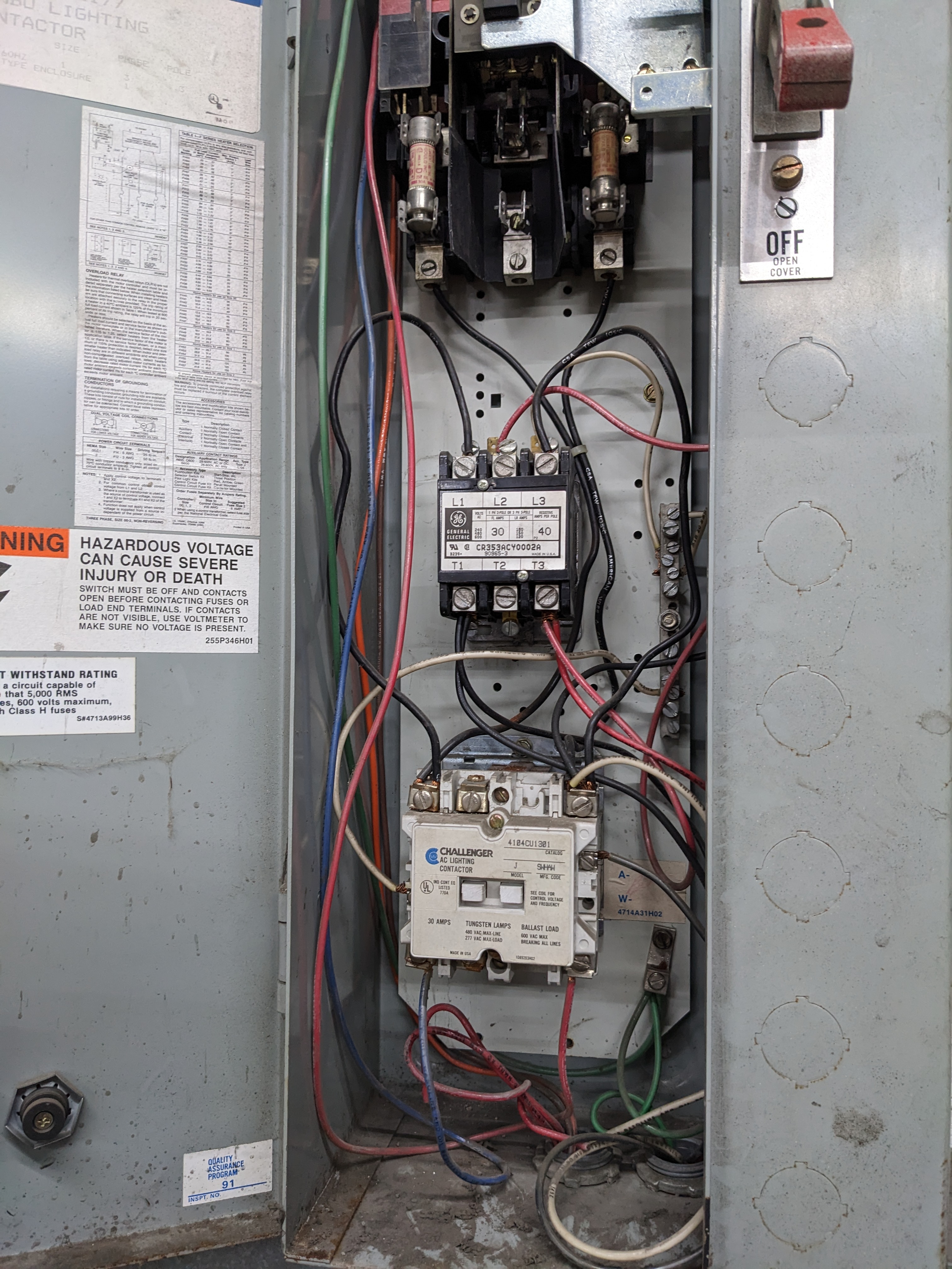
Challenger Contactor - unknown if original configuration

Learn the NEC with Mike Holt now!
Status
Not open for further replies.

Llortus

Member
Location
Beaver, PA
Occupation
Retired Electrician/Lineman
FullView.jpg

This is in a friends warehouse, traced all the high bay mercury vapor (white bulb) lights to this contactor.

Someone has been into this system and has wired some LED lights, I'm assuming because they couldn't figure out contactor. I suspect they may of grabbed power from previous control circuit.

Warehouse is single phase 120/240, contactor fed with double pole 20A breaker.

When the contactor was manually activated it tripped the 20A breaker.

I can confirm we had voltage at load side of fuses and bottom blue and red wires feed the lights.

Looking for:
What control scheme do you think this is using?

Do you see wiring issues that don't look right?
 
What is the white wire on the top right of the contactor connected to? What is the voltage range of the LED's?
 
It has the original wiring diagram on the door
Looking at that diagram made me think originally these relays were supposed to work together with some type of control scheme like push button control. Tried looking up Challenger Contactor to determine if it was magnetic latching or not. No luck. Current wiring configuration would have me think that they are unrelated contactors placed in same panel with 120V needing to be maintained to keep contactor latched? But the wires in panel do not look like they were installed this way originally, looks like someone has moved the wires around like it was a training panel.
 
Looking at that diagram made me think originally these relays were supposed to work together with some type of control scheme like push button control. Tried looking up Challenger Contactor to determine if it was magnetic latching or not. No luck. Current wiring configuration would have me think that they are unrelated contactors placed in same panel with 120V needing to be maintained to keep contactor latched? But the wires in panel do not look like they were installed this way originally, looks like someone has moved the wires around like it was a training panel.
If it was a latching contactor, it would not have released when you operated it manually.

The contactor should not have voltage on its load side terminals if its power contacts are open. Is it being backfed, causing a short when it is closed?

Have you opened the contactor to look at its contacts?
 
Is the General Electric CR353ACY0002A meant to be an overload relay? My son recently turned me onto Chat GPT and it gave me this information on the GE relay:
The General Electric (GE) part number CR353ACY0002A is a combination lighting contactor and overload relay. The part number can be broken down into several components, each of which provides information about the product.

Here's a breakdown of the part number:

  • CR353: This is the product family code for combination lighting contactors and overload relays.
  • A: The next letter indicates the type of coil voltage for the device. In this case, "A" represents an alternating current (AC) coil voltage.
  • CY: The next two letters indicate the specific features and ratings of the product. In this case, "CY" indicates that the device has a compact size and a control voltage of 24V AC.
  • 0002: This is the catalog number of the product within the product family.
  • A: The final letter is the revision code, which indicates the version of the product.
In conclusion, the GE part number CR353ACY0002A is a combination lighting contactor and overload relay with an AC coil voltage, a compact size, a control voltage of 24V AC, and a catalog number of 0002. The final letter "A" indicates that this is the latest revision of the product.
 

Attachments

  • GE Definite Purpose Controls - Contactors, Starters, 2-Speed Controllers Renewal Parts_ GEA-11...pdf
    220.3 KB · Views: 8
If it was a latching contactor, it would not have released when you operated it manually.

The contactor should not have voltage on its load side terminals if its power contacts are open. Is it being backfed, causing a short when it is closed?

Have you opened the contactor to look at its contacts?
It released because the breaker feeding panel tripped.
Before manually operating it only had voltage on top relay on L1 and L3 and the L1 and L3 of bottom contactor.
I wanted to do some research before disassembling.
 
It released because the breaker feeding panel tripped.
Before manually operating it only had voltage on top relay on L1 and L3 and the L1 and L3 of bottom contactor.
I wanted to do some research before disassembling.
Latching contractors will stay closed even with power removed. It sounds like yours is electrically held.

You should not have voltage on the load terminals with the contactor not closed. What needs to be turned off to have this voltage disappear? What voltage do you measure from the line side to the load side terminals?
 
Last edited:
It's a CF someones have modified more than once, and not even close to correct.

Start over with what the customer wants it to do now.
Took awhile for me to figure out what type of control scheme CF stood for, your right it is a mess. The customer just wants lights. He would be fine with using the disconnect switch to turn lights on and off.
 
They are both just simple 3 pole contactors, no latching feature, no overload components. Send proper coil voltage to the coil terminals and the three power contacts close, remove coil voltage the contacts open.

Looks like neutral conductor is tied to what should be the EGC, doubt this is service equipment so grounded and equipment grounding conductors should not intermix at this location.
 
Took awhile for me to figure out what type of control scheme CF stood for, your right it is a mess. The customer just wants lights. He would be fine with using the disconnect switch to turn lights on and off.
Simple two pole toggle switch would cost a lot less than that setup, especially if all that is wanted is a single manually operated handle to turn the lights on or off. Maybe a second switch if whatever is controlled by the second contactor is desired to be separately switched, but both are on the same overcurrent devices. I guess you still would need overcurrent device(s) if this is tapped from a higher capacity feeder though.
I certainly wouldn't replace it with a lighting contactor if it needed replacing and a single operating mechanism is all that is desired
Isolated a 400W Metal Halide Fixture shorted and connected the rest of the lights below fuses. removing the relays from play. I can't figure out what they were trying to do; but he can turn the lights on now.
 
W
FullView.jpg

This is in a friends warehouse, traced all the high bay mercury vapor (white bulb) lights to this contactor.

Someone has been into this system and has wired some LED lights, I'm assuming because they couldn't figure out contactor. I suspect they may of grabbed power from previous control circuit.

Warehouse is single phase 120/240, contactor fed with double pole 20A breaker.

When the contactor was manually activated it tripped the 20A breaker.

I can confirm we had voltage at load side of fuses and bottom blue and red wires feed the lights.

Looking for:
What control scheme do you think this is using?

Do you see wiring issues that don't look right?
When you say manually activated, do you mean electrically? Or mechanically? (Screwdriver pushing plunger in)
 
They are both just simple 3 pole contactors, no latching feature, no overload components. Send proper coil voltage to the coil terminals and the three power contacts close, remove coil voltage the contacts open.

Looks like neutral conductor is tied to what should be the EGC, doubt this is service equipment so grounded and equipment grounding conductors should not intermix at this location.
Betting the lights were all 240 volt, and no neutral is present, so the just grabbed the ground for the 120 volt contactor coil. Definitely need to change both contactors to 240 volt coils. With voltages the op is getting, probably bucking phases with another circuit when the contacts are closed, since the “line” side of the bottom contactor is fed from the line side of the top contactor.
 
Status
Not open for further replies.
Top