It's official, I must be crazy if I'm the only one who has a problem with this.
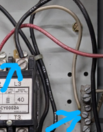
The line from the fuse goes directly to top right connector of the contactor.
View attachment 2563992
That is where I would expect it to land
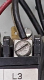
This is a close up of a similar contactor terminal.
View attachment 2563993
That is coil terminal, other coil terminal is on opposite side.
This terminal is connected directly to the top right terminal of the overload relay (or whatever its called)
View attachment 2563994
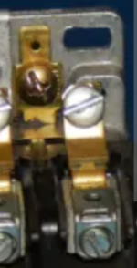
Here is a close up of what that terminal looks like on the exact model.
View attachment 2563995
The further back terminal there is a coil terminal, the further forward terminals are power pole terminals.
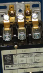
That terminal is connected directly to the neutral bar
View attachment 2563996
As mentioned that is likely an EGC bar and not a neutral bar, unless it would happen to be service equipment. That kind of tells us the contactor likely has a 120 volt coil even though it should be connected to a neutral and not an EGC.
If I'm wrong about this please explain it to me. Either way I won't harp on it anymore.