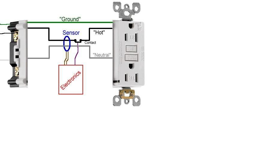
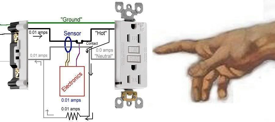
Let's take a standard GFCI receptacle and take it apart. Inside you will find an electronics board (an IC to some of you), a sensor, and a contact. Since the innards of an actual GFCI are quite complicated, I'll use my crude drawing to make things (hopefully) a little more clear.
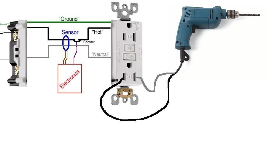
Now, let's plug in a power tool, with the assumption that the tool is safe to use.
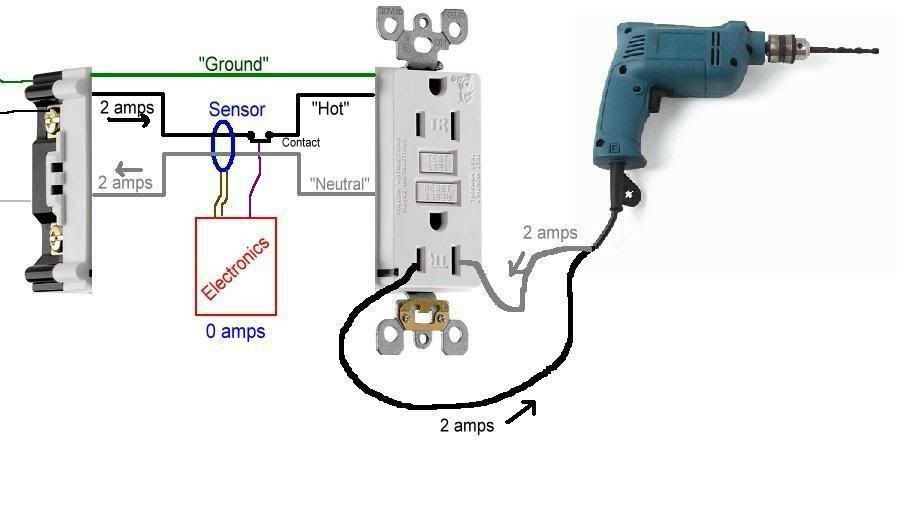
When you turn the drill on, it draws current through the entire circuit.... the 'hot' and 'neutral' conductors both have the same amount of current flowing through them, only in opposite directions.
Since the same amount of current is flowing through both the hot and neutral, they will cancel each other out and the sensor will detect 0.0 amps. If this sensor detects more than 0.005 amps (5mA), then the electronics picks this up and will open the contact, turning power off to the outlet.
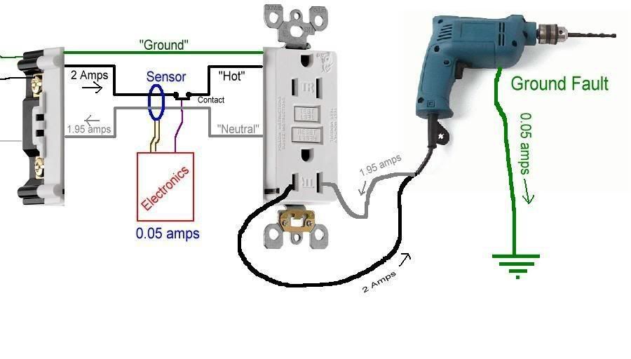
So let's do just that. Let's say there's a problem with the cord or the metal case of the drill (yea, I know, the drill looks like it's plastic, but let's pretend it's metal), and a ground fault exists between it and a ground. Now, current will flow through the hot, and to the ground fault. Let's say the fault current is 0.05 amps.
The drill will still run properly, but part of the current it consumes does not return through the proper path (the neutral). Instead, it flows through the ground fault.
The sensor will detect an imbalance of 0.05 amps, and the electronics will open the contact and turn of the power.
This is the primary and sole function of GFCI protection. It is assumed a ground fault is going through a human being and turn the power off. Only when the fault is removed will the ability to restore power with the 'Reset' button work. The GFCI does not care whether there actually is a human getting shocked or not. It could be the end of a cord is lying in a puddle of water. It could be a fault the operator of the drill is not a part of. Nonetheless, once more than 0.005 amps flows through a ground fault, the GFCI opens.
Now, in order to test a GFCI receptacle, the manufacturers put in a handy-dandy Test button. What this test button does is create a small current flow (using a resistor to simulate a load with a ground fault) that intentionally bypasses part of the sensor, forcing it to sense that imbalance. If the GFCI sensor, contact, and electronics are functioning properly the power will be shut off.
Now, up until this point, you will notice the 'Ground' wire has not been mentioned, nor has any current flowed along it. Point is, none needs to. The ground wire is there to open the breaker or fuse if there is a fault
within the wiring beyond the receptacle. If the drill was shorted internally, then the ground would carry enough current to cause the breaker or fuse to open and turn off the power.
The ground wire is for the operation of the breaker or fuse, NOT the GFCI. If no ground wire existed to feed this receptacle, the GFCI will still function as designed...... sensing imbalances and turning power off in a ground-fault situation.
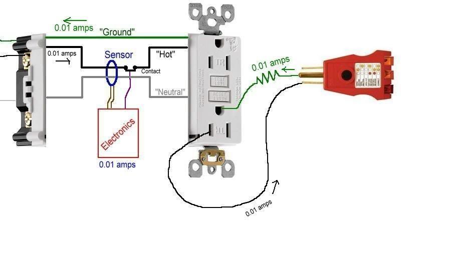
The only function a ground wire has in the operation of a GFCI is when a plug-in tester is used to test a GFCI.
One important note here; the industry standard is to use only the built-in Test button to check for proper function. UL does not recognize using plug-in testers as a proper method of testing GFCIs.
With a properly-wired (3-wire) GFCI receptacle, the only way a plug-in tester can safely simulate an imbalance is to induce it through the ground. It has to, since it cannot bypass the sensor using the neutral. If you placed the resistor between the hot and neutral, the GFCI would only 'see' it as any other load, as the current flow between the hot and neutral would be equal and cancel each other out at the sensor.
With the plug-in tester, the current flows out through the hot, and back through the ground. Since current flow on the ground is not going through the sensor, only the current on the hot is detected. With no opposing return current flow to balance it out, the electronics assume a ground fault and opens the contact... turning power off.
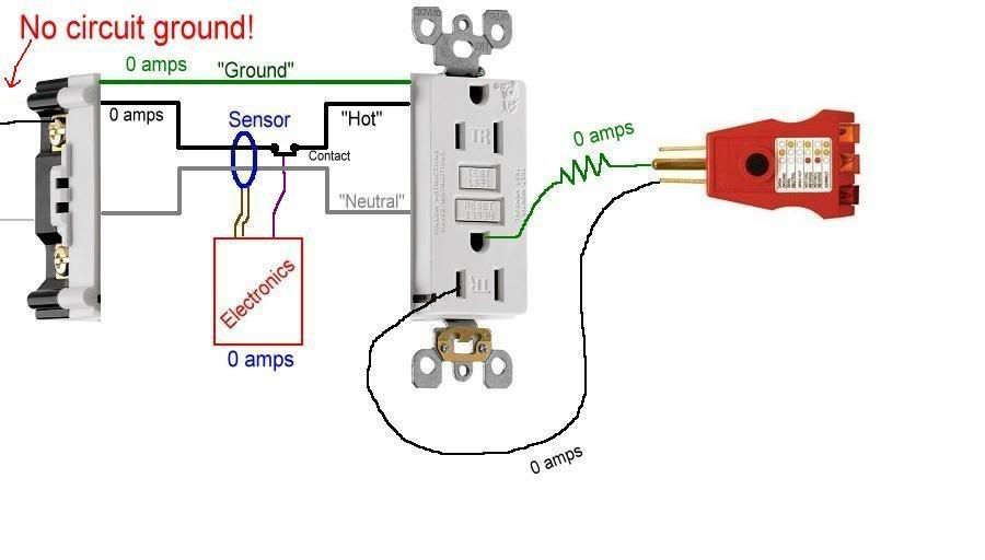
If you only have a 2-wire (ungrounded) circuit, then the plug-in tester cannot create a current flow on the ground as the ground is not there. Since no current can flow in this incomplete circuit, the GFCI will sense 0.0 flow and not open the contact.
There are other things today's GFCIs do that are not relevant to the discussion here, but I'll mention them here.
One is Loss of Neutral. The electronics can sense the loss of the circuit's neutral, and will open the contact. The reason being, if there is no neutral, the electronics cannot function in order to open the contact in the event of a ground fault. So if the neutral feeding the circuit opens, the GFCI will turn the power off.
Another is a self-test function. If the internal wiring of the GFCI becomes damaged (either physically or, say, a surge due to lighting), the power will shut off as well. Pushing the Reset button will not reset it.... it will stay off and need to be replaced.
Another important function is Line-Load and Hot/Neutral Miswire detection. If the power to the receptacle is mistakenly attached to the Load terminals, or if the hot and neutral are reversed on the Line terminals, the GFCI will detect these installation errors as well and will not turn on until the problem(s) is (are) corrected. This is to ensure the GFCI is wired correctly at initial install to provide proper protection for the life of the unit.
Most GFCI receptacles today are also Tamper-Resistant (notice the TR on the face) to keep foreign objects from being pushed into the slots, and GFCIs are available in Weather-Resistant versions for installation in damp and wet locations.
OK, school is out.

")