Computing short circuit current of Open Delta 3 phase transformers

Status
Not open for further replies.

tersh

Senior Member
Location
new york
For a 3 phase open delta transformers:


0zgJjs.jpg


When you are computing the short circuit current between the 208v high leg (point B) and neutral. Do you only use one 75kVA or do you add the other transformer to produce for example 75kVAx1.5 (or other value) = 112.5kVA? What exact values you use?

I'm thinking if one needs to add because between point B and neutral, there are more than 1 winding (or 1 transformer) involved. What do you think?
 

kwired

Electron manager
Location
NE Nebraska
I'm thinking the total transformer impedance in this calc is 1.5 x the 75 kVA impedance. It's one winding in series with a half winding.
First, kudos to tersh for starting a new thread, this is discussion that started in another thread.

I have always wondered exactly how one should figure impedance on such systems. Your answer is what I assumed would be correct but never really got any verification on this in the past when asking about it.

Now to throw in a few variances that still have me wondering at times..

Say drawing in OP were full delta with three of the same transformers.

in that case you have parallel paths for current if you have a fault from high leg to neutral. An additional transformer surely increases total kVA, does it change impedance? My guess is yes. Probably still 1.5 times one coil but then figured similar if not same as figuring resistance of two resistors in parallel.

If my suspicion on that is correct it probably answers some of my other variances -

different sized transformer for the high leg, full delta with large lighting pot and two smaller pots for the rest of the delta, even kind of wondered if a wye bank of transformers should consider the fact you have three separate paths with three separate impedances in parallel if you have a bolted three phase fault. I think a lot of guys just look at the impedance on the nameplate of one unit in that situation and plug that into their fault current calculator though it probably isn't correct for a line to line fault - would apply to a line to neutral fault though.
 

tersh

Senior Member
Location
new york
First, kudos to tersh for starting a new thread, this is discussion that started in another thread.

I have always wondered exactly how one should figure impedance on such systems. Your answer is what I assumed would be correct but never really got any verification on this in the past when asking about it.

Now to throw in a few variances that still have me wondering at times..

Say drawing in OP were full delta with three of the same transformers.

in that case you have parallel paths for current if you have a fault from high leg to neutral. An additional transformer surely increases total kVA, does it change impedance? My guess is yes. Probably still 1.5 times one coil but then figured similar if not same as figuring resistance of two resistors in parallel.

If my suspicion on that is correct it probably answers some of my other variances -

different sized transformer for the high leg, full delta with large lighting pot and two smaller pots for the rest of the delta, even kind of wondered if a wye bank of transformers should consider the fact you have three separate paths with three separate impedances in parallel if you have a bolted three phase fault. I think a lot of guys just look at the impedance on the nameplate of one unit in that situation and plug that into their fault current calculator though it probably isn't correct for a line to line fault - would apply to a line to neutral fault though.

Here is the actual nameplate I took picture in the actual transformers used (before they were put in the pole that day).

Rkv4W9.jpg


F8e7Cb.jpg


What do you make of it? Assuming infinite bus, can you help compute for the short circuit current of the transformers load side (ignoring all conductors)?

I'm using rough 75,000/208/0.0259 = 13,921A short circuit infinite bus assumption.. but if the impedance has to be multiply by 1.5X then it becomes:

75,000/208/0.03885= 9281A only?

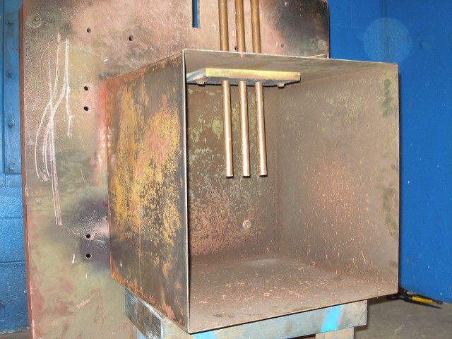
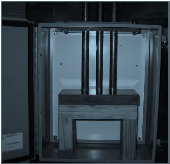
But in IEEE-1584-2002. They used test setup with open space (below), but when barrier like breaker top was put inside, 208v can arc flash even with 2000A bolted short circuit current at 12mm gap.

sG0Bqu.jpg
 

Julius Right

Senior Member
Occupation
Electrical Engineer Power Station Physical Design Retired
If the transformer shown in #4 is the actual in the open post this is not a 3 phase transformer in open delta but a single phase transformer. In the nameplate it is not mention any grounding in the low voltage windings.
Single phase noopen delta.jpg
 

tersh

Senior Member
Location
new york
If the transformer shown in #4 is the actual in the open post this is not a 3 phase transformer in open delta but a single phase transformer. In the nameplate it is not mention any grounding in the low voltage windings.
View attachment 22537


It's the actual transformer. There were two like it. This is the 1st one (I traced the 3 phases late last year):

SZeMiH.jpg


The identical transformer at the back has the grounding at the centertap:

6rdggg.jpg


The following was the bottom view of it where the centertap ground wire was connected to the multiple neutral network which has rods besides the poles:

hCpe0A.jpg


The reason it was really an open delta 3 phase was because in 2015, the electrician measured the 3 phases to neutral. One was 208v, the others were 120v.

ivRTTS.jpg


X1 (right most wire) to neutral was measured as 208 Volts.
X2 to neutral was measured as 120 volts.
X3 (left most wire) to neutral was measured as 120 volts.

But between X1-X2, X1-X3, X2-X3.. they are all 240 volts.
 

kwired

Electron manager
Location
NE Nebraska
If the transformer shown in #4 is the actual in the open post this is not a 3 phase transformer in open delta but a single phase transformer. In the nameplate it is not mention any grounding in the low voltage windings.
View attachment 22537

The question is what is the impedance involved of a high leg to neutral fault on the secondary when two of those single phase transformers are used to build an open delta bank? Yes the nameplate tells you impedance of that particular unit by itself. If you are connecting them so the secondaries are an open delta, and you have a high leg then the mid point of one unit is grounded and the high leg is the opposite corner of the delta from that grounded midpoint. You can only ground one point of the system or you will have fault current between any multiple grounded points.
 

Julius Right

Senior Member
Occupation
Electrical Engineer Power Station Physical Design Retired
Vbn=Vab+Vca/2 Vab=240 Vac=-120+207.85i Vbn=180+103.92i=207.85<30
Zbn=Zab+Zan=1.5*Zab
Po=noload losses=43 W ; Pload=full load losses=758 W
Pcu=copper losses=Irat^2*Rcu ; Pload=Irat^2*Rcu+Po ; Rcu=(Pload-Po)/Irat^2
Irat=312.5 A ; Rcu=0.007322 ohm
Zab=Vab^2/S*imp%/100=0.240^2/0.075*2.59/100=0.019891ohm
Xab=√(Zab^2-Rcu^2)=0.018495 ohm
Zab=0.007322+0.018495i ohm
Iscbn=Vbn/1.5Zab=5459.09-4327.2i [6966.1<-38.4o]

Open delta short circuit current.jpg
 

tersh

Senior Member
Location
new york
Vbn=Vab+Vca/2 Vab=240 Vac=-120+207.85i Vbn=180+103.92i=207.85<30
Zbn=Zab+Zan=1.5*Zab
Po=noload losses=43 W ; Pload=full load losses=758 W
Pcu=copper losses=Irat^2*Rcu ; Pload=Irat^2*Rcu+Po ; Rcu=(Pload-Po)/Irat^2
Irat=312.5 A ; Rcu=0.007322 ohm
Zab=Vab^2/S*imp%/100=0.240^2/0.075*2.59/100=0.019891ohm
Xab=√(Zab^2-Rcu^2)=0.018495 ohm
Zab=0.007322+0.018495i ohm
Iscbn=Vbn/1.5Zab=5459.09-4327.2i [6966.1<-38.4o]

View attachment 22538

So what is the short circuit current of the open delta above? I guess below 10kA?

I understand higher impedance means the short circuit current in open delta is smaller. But in case there would be a transient while the short circuit occurs, would it increase the short circuit current by maybe 4 to 5 times?
 

tersh

Senior Member
Location
new york
Let's say the short circuit current of the above open delta transformers is 6970 Amps.

Given there is 23 feet of AWG 1 conductors to the region or parts where bolted short occurs. How do you include the conductor impedance to the source impedance to get an overall decreased scc? And how much is the decreased bolted short circuit current? How do you compute for it?

I just read the full paper called "Investigation of Factors Affecting the Sustainability of Arcs Below 250 V" by Michael J. Lang, Member, IEEE, and Kenneth Jones, Member, IEEE at Library Genesis.

The contents are horrifying. Here they used setups representative of real world equipments.

2Eg6l3.jpg


quoting their finding a bit:

"Tests performed with gaps of 12.7 and 50.8 mm were used to determine the effects of gap and X/R ratio on arc sustainability and incident energy with the barrier in place. Testing at progressively lower currents revealed the barrier configuration’s ability to reliably sustain arcs for more than 1 s with a 12.7-mm gap at 4 kA and 208 V. The 32-mm gap performed intermittently at the lower values."

Here is the abstract:

"Abstract—Recent testing with various electrode configurations and insulating barriers suggests that 250-V equipment omitted from arc flash hazard analyses has the potential for burn injury. Research into the sustainability of arcs at these voltages shows that assumptions about the magnitude of these hazards need to be revised. This research enhanced the work of previous efforts by focusing on the sustainability of arcs with fault currents lower than 10 kA. Gap lengths between electrodes, electrode shape, electrode material, and voltage variations are studied for their effects on arc sustainability. A modified barrier design representative of the space around panelboard bus bars is also studied."

The following is their conclusion:

"CONCLUSION

The testing discussed in this paper shows that sustained arcs are possible at 208 V even at relatively low fault currents but are dependent on several factors including voltage variations, conductor material, the configuration of conductors, and the presence of insulating barriers. The challenge to industry is to advance the research identified in the references, do additional testing on a variety of low-voltage equipment, and incorporate those findings into improved standards. These test strategies must consider all practical locations within the equipment where arcs may occur; within all equipment is the possibility for different electrode orientations.
Enhanced models for various equipment"
 

Julius Right

Senior Member
Occupation
Electrical Engineer Power Station Physical Design Retired
According to IEEE 80/2013 formula (79):
if(t)=√2*Vbn/1.5/Zab.[sin(ωt+α-θ)-e^(-t/Ta)sin(α-θ)]
it is maximum for α=12 degrees [at time t=0.006173 s]
α is the voltage angle at current initiation in radians=0.20944
θ is the circuit phase angle in radians=(30+38.4)=68.4 degrees=1.193805 rad
Then Iscbn=12862.4 A -in my opinion it could be the maximum short-circuit instantaneous current.
The integrated energy current according to formula 84 for decrement factor
Df=√[1+Ta/tf*(1-e^(-2tf/Ta)]
If a very fast switch will act in 0.001 s then Df=1.652 [approx.7000*1.652=11564 A]
 

tersh

Senior Member
Location
new york
According to IEEE 80/2013 formula (79):
if(t)=√2*Vbn/1.5/Zab.[sin(ωt+α-θ)-e^(-t/Ta)sin(α-θ)]
it is maximum for α=12 degrees [at time t=0.006173 s]
α is the voltage angle at current initiation in radians=0.20944
θ is the circuit phase angle in radians=(30+38.4)=68.4 degrees=1.193805 rad
Then Iscbn=12862.4 A -in my opinion it could be the maximum short-circuit instantaneous current.
The integrated energy current according to formula 84 for decrement factor
Df=√[1+Ta/tf*(1-e^(-2tf/Ta)]
If a very fast switch will act in 0.001 s then Df=1.652 [approx.7000*1.652=11564 A]

I let an EE at stack exchange compute for it. This is what he said (how come his value different from yours)?

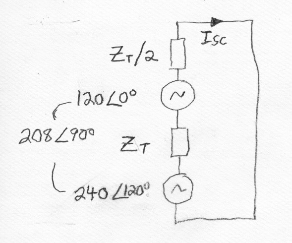
"To calculate the current in a short circuit between point B and the center tap of the A to C winding I would first calculate the winding impedance. The full 240 volt winding is rated 75 kVA. The impedance of a load that would draw 75 kVA is 240^2/75000 = 0.768 ohms. The transformer impedance is 2.59% or 0.0259 x 0.768 = 0.0199 ohms. The total impedance of a 120 V winding in series with a 240 V winding is 1.5 x 0.0199 = 0.0298 ohms. The short circuit current would then be 208/.0298 = 6971 amps.

I used the percent impedance to calculate impedance in ohms because the percent impedance is based on 75 kVA at 240 volts and the combination of windings results in 208 volts. It seems easier and more clear to used a fixed ohmic value when dealing with one single-phase transformer and part of another connected to three-phase power.

I believe the equivalent circuit is a shown below. Each transformer or part of a transformer is represented as an ideal voltage source and an impedance. The impedance of the 3-phase source is assumed to be zero."

mRPspy.jpg


tersh

Senior Member
Location
new york
Do you guys agree that conductor impedance would have insignificant effect on the bolted short circuit current?

For 23 feet of wires (see https://www.cirris.com/learning-center/calculators/133-wire-resistance-calculator-table)

impedance is 0.003 ohm...

adding it to the impedance of the transformers produce
0.003 + 0.0298 = 0.0328

and dividing 208v by 0.0328 = 6341 amps.

So the wires decrease the short circuit current of the transformer by only 6971 - 6341 = 630

6341 amps is still big.

The latest IEEE 1584-2018 concludes from additional experiments that 2kA is enough to cause arc flash if the panel has any breakers. They admit the original IEEE 1584-2002 used and assumed empty panel hence had flaws. My actual case proved it.
 

kwired

Electron manager
Location
NE Nebraska
Do you guys agree that conductor impedance would have insignificant effect on the bolted short circuit current?

For 23 feet of wires (see https://www.cirris.com/learning-center/calculators/133-wire-resistance-calculator-table)

impedance is 0.003 ohm...

adding it to the impedance of the transformers produce
0.003 + 0.0298 = 0.0328

and dividing 208v by 0.0328 = 6341 amps.

So the wires decrease the short circuit current of the transformer by only 6971 - 6341 = 630

6341 amps is still big.

The latest IEEE 1584-2018 concludes from additional experiments that 2kA is enough to cause arc flash if the panel has any breakers. They admit the original IEEE 1584-2002 used and assumed empty panel hence had flaws. My actual case proved it.
Conductor impedance has a big impact on amount of fault current. Assuming you are correct with your calculations - 630 amps is about 10% difference in transformer terminal available current and end of the conductors available current.

Though I'm not certain your calculation is correct. .003 ohms of conductor seems like a reasonable figure, but is .0298 you added to it the transformer ohms or is it 2.98% impedance marked on transformer nameplate?
 

tersh

Senior Member
Location
new york
Conductor impedance has a big impact on amount of fault current. Assuming you are correct with your calculations - 630 amps is about 10% difference in transformer terminal available current and end of the conductors available current.

Well.
6971amp vs 6341 amp (with 23 feet conductor impedance) is not huge difference considering the new IEEE 1584-2018 already considered 208v above 2ka as able to produce arc flash.


Though I'm not certain your calculation is correct. .003 ohms of conductor seems like a reasonable figure, but is .0298 you added to it the transformer ohms or is it 2.98% impedance marked on transformer nameplate?

Here is the formula taught to me by an EE:

"To calculate the current in a short circuit between point B and the center tap of the A to C winding I would first calculate the winding impedance. The full 240 volt winding is rated 75 kVA. The impedance of a load that would draw 75 kVA is 240^2/75000 = 0.768 ohms. The transformer impedance is 2.59% or 0.0259 x 0.768 = 0.0199 ohms. The total impedance of a 120 V winding in series with a 240 V winding is 1.5 x 0.0199 = 0.0298 ohms. The short circuit current would then be 208/.0298 = 6971 amps."
 

tersh

Senior Member
Location
new york
Well.
6971amp vs 6341 amp (with 23 feet conductor impedance) is not huge difference considering the new IEEE 1584-2018 already considered 208v above 2ka as able to produce arc flash.


Here is the formula taught to me by an EE:

"To calculate the current in a short circuit between point B and the center tap of the A to C winding I would first calculate the winding impedance. The full 240 volt winding is rated 75 kVA. The impedance of a load that would draw 75 kVA is 240^2/75000 = 0.768 ohms. The transformer impedance is 2.59% or 0.0259 x 0.768 = 0.0199 ohms. The total impedance of a 120 V winding in series with a 240 V winding is 1.5 x 0.0199 = 0.0298 ohms. The short circuit current would then be 208/.0298 = 6971 amps."

Here is an online Fault Current Calculation Sheet I tried:

https://electrical-engineering-port...electrical-software/fault-current-calculation

confirming my manual computations.

yf3NKm.jpg


VsA1fB.jpg
 

kwired

Electron manager
Location
NE Nebraska
That is same spreadsheet I used when replying in the other thread before you opened this thread. I told you there that it wasn't necessarily accurate for multiple single phase transformers banked to make a three phase source.

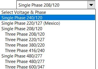
You might be able to tweak the variables you input and come closer, but appears you plugged in available fault current for a single 75 kVA transformer, when in reality you have 1.5 times that kVA involved with the high leg to neutral, you then told the spreadsheet you have three phase 208/120, when what you are calculating is more like 208 single phase, though that is not one of the system voltages available to select.

Maybe use of single phase 220/127 and 1.5 times the single unit impedance gives you much closer to actual fault current on the high leg? Line to neutral current with that input is meaningless as it would be at a point in the system where there is no utilization tap.

It still won't be accurate, but if you are trying to figure out a worst case scenario for the purpose of selecting appropriate PPE, it should be off in the right direction for safety sake.

Open delta is not so common to even non existent in some areas, and very common in others.
 

tersh

Senior Member
Location
new york
That is same spreadsheet I used when replying in the other thread before you opened this thread. I told you there that it wasn't necessarily accurate for multiple single phase transformers banked to make a three phase source.

You might be able to tweak the variables you input and come closer, but appears you plugged in available fault current for a single 75 kVA transformer, when in reality you have 1.5 times that kVA involved with the high leg to neutral, you then told the spreadsheet you have three phase 208/120, when what you are calculating is more like 208 single phase, though that is not one of the system voltages available to select.

Maybe use of single phase 220/127 and 1.5 times the single unit impedance gives you much closer to actual fault current on the high leg? Line to neutral current with that input is meaningless as it would be at a point in the system where there is no utilization tap.

It still won't be accurate, but if you are trying to figure out a worst case scenario for the purpose of selecting appropriate PPE, it should be off in the right direction for safety sake.

Open delta is not so common to even non existent in some areas, and very common in others.

oWFnrL.jpg

Zu30eI.jpg


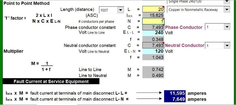
I'm computing everything manually, comparing it with the arc flash fault excel sheet above and stuck on a point. I used just single phase 240/120v for simplicity. I even discussed with an EE not familiar with arc flash calculations but just using logic. He said resistance of wire is almost insignificant compared to the inductance or impedance of the transformer. Lets give numeric example of a single phase 240/120v transformer.

For the above excelsheet transformer terminal short circuit current of 15625amp (Isca),

computing using the infinite bus short cut method

75,000/240/0.02=15625 amp

or the long cut (with derivation) method

kVa = 75,000
voltage =240v
The impedance of a load that would draw 75 kVA is 240^2/75000 = 0.768 ohms.
Transformer impedance = 0.02x 0.768 = 0.01536
Short circuit current = 240v/0.01536 = 15625 amp

Now consider 20 feet of wire has resistance of about 0.005 (from an online wire impedance calc)

To add them together one, one uses this
Total impedance = sqrt (0.005^2 + 0.01536^2)= 0.016153

bolted short circuit current is 240/0.016153= 14,858 amp

In the excel file 20 feet has bolted short circuit current of 11,595 amp.

Did it somehow give the 20 feet conductor an inductive value, but it's not part of the transformer winding.

Can you or anyone explain or show how the excel sheet 11,595 amp is derived manually and derivations from first principles?
 

tersh

Senior Member
Location
new york
oWFnrL.jpg

Zu30eI.jpg


I'm computing everything manually, comparing it with the arc flash fault excel sheet above and stuck on a point. I used just single phase 240/120v for simplicity. I even discussed with an EE not familiar with arc flash calculations but just using logic. He said resistance of wire is almost insignificant compared to the inductance or impedance of the transformer. Lets give numeric example of a single phase 240/120v transformer.

For the above excelsheet transformer terminal short circuit current of 15625amp (Isca),

computing using the infinite bus short cut method

75,000/240/0.02=15625 amp

or the long cut (with derivation) method

kVa = 75,000
voltage =240v
The impedance of a load that would draw 75 kVA is 240^2/75000 = 0.768 ohms.
Transformer impedance = 0.02x 0.768 = 0.01536
Short circuit current = 240v/0.01536 = 15625 amp

Now consider 20 feet of wire has resistance of about 0.005 (from an online wire impedance calc)

To add them together one, one uses this
Total impedance = sqrt (0.005^2 + 0.01536^2)= 0.016153

bolted short circuit current is 240/0.016153= 14,858 amp

In the excel file 20 feet has bolted short circuit current of 11,595 amp.

Did it somehow give the 20 feet conductor an inductive value, but it's not part of the transformer winding.

Can you or anyone explain or show how the excel sheet 11,595 amp is derived manually and derivations from first principles?

Here's the calculation reference so you can easily create your own spreadsheet (I just entered it at excel).

http://www.cooperindustries.com/con...rary/BUS_Ele_Tech_Lib_Electrical_Formulas.pdf

Let's focus on single phase line to line

1Ø Line-to-Neutral (L-N) Faults

f = [2 x L x I (l-l)] /[ C x n x E (l-)]

Where:

L = length (feet) of conductor to the fault.
C = constant from Table 4 of “C” values for conductors and
Table 5 of “C” values for busway.
n = Number of conductors per phase (adjusts C value for
parallel runs)
I = Available short-circuit current in amperes at beginning
of circuit.
E = Voltage of circuit.

How did they determine C because the bolted short circuit current is much lower using this method but high when directly computing for it (in my last message)?
 
Status
Not open for further replies.
Top