Computing short circuit current of Open Delta 3 phase transformers

Status
Not open for further replies.

Julius Right

Senior Member
Occupation
Electrical Engineer Power Station Physical Design Retired
Here attached it is an explanation for my post no.11:
Short circuit current instantaneous curve.jpg
 

tersh

Senior Member
Location
new york

Can you share it with words?

I'm still trying to figure out the voltage drop of 20 feet of awg 1 conductors. The arc itself has contributions but I don't know how much compared to the wire contribution in voltage drop hence manually computing and verifying:

n390zd.jpg
 

tersh

Senior Member
Location
new york
I'm looking for derivations of f and M in the arc flash point to point method of computation of bolted short circuit current at the panel


sGFlK8.jpg


I have already derived C which is just 1/Z

http://www.cooperindustries.com/con...rary/BUS_Ele_Tech_Lib_Electrical_Formulas.pdf

https://peritoselectricos.mx/wp-con...ay-Electric-Power-Systems-in-Commercial-B.pdf

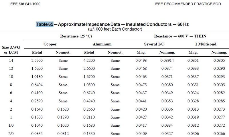
Table 65: at 1000 feet

Resistance is 0.129 ohm

Reactance is 0.0342

For 1 foot.. resistance is 0.129 ohm * 1/1000= 0.000129 ohm
reactance at 1 foot is 0.0000342

Impedance = sqrt (0.000129^2+0.0000342^2) = 0.0001335 ohm

1/Z = 1/0.0001335 = 7493 which is the C listed for AWG 1 Cooper nonmetallic 600v in the 1st link above.

now going to the formula f = [1.732 * L * I] /[ N * C * E(l-l)]

since C = 1/Z. We could use 1/Z

This would make the equation f = [1.732 * L* Z* I] / [N* E(l-l)]

Since L is just length of conductors
N is number of conductors per phase
E(l-l) is just the voltage line to line
I is the short circuit current
Z is impedance
1.732 is just sqrt (3)

it looks like the equation doesn't take into account the following arc flash dynamics:

1. arc flash added impedance
2. heating up lowering threshold voltage
3. arc gap causing voltage drop

Does it? If these are not included in the equations of f and M, then it means the actual bolted short circuit current is lower?
 

tersh

Senior Member
Location
new york
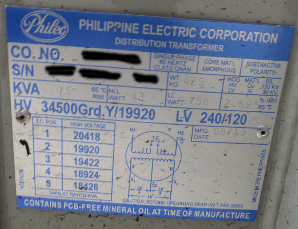
What is the exact X/R ratio of this transformer or similar class of transformers?

Rkv4W9.jpg


Using direct impedance computations from the table. The bolted short circuit current varies the ones with f and M (point to point method) by a wide margin.

So I need to know the exact X/R ratio of the transformers to know the contribution of resistance and inductance to the transformer given impedance to get more accurate results.

Let's compute the IEEE f and M and compare it to the total impedances to get at the bolted short circuit current. Let's just use simple single phase 240/120 with 75kVA and 2% impedance with X/R mostly in the inductive reactance side.

https://peritoselectricos.mx/wp-content ... cial-B.pdf

Table 65 for AWG 1 at 1000 feet for Nonmetallic conductors and Several 1/C Nonmagc conductor Data

ucxvTb.jpg


Resistance is 0.129 ohm
Reactance is 0.0342

For 1 foot:
resistance is 0.129 ohm * 1/1000= 0.000129 ohm
reactance is 0.0342 * 1/1000 = 0.0000342

Impedance = sqrt (0.000129^2+0.0000342^2) = 0.0001335 ohm

1/Z = 1/0.0001335 = 7493 which is the C listed for AWG 1 Cooper nonmetallic 600v in the cooper pdf (see my last message for the table)

now going to the formula f = [1.732 * L * I] /[ N * C * E(l-l)]

entering the above data,
f is 0.347,
M = 0.742
Isc (bolted scc) = 11597 amp

This is same result in the IEEE 1584-2002 spreadsheet

Now if you will compute it directly by getting the impedances of the wires and transformers and dividing 240v by the total impedances to get the bolted short circuit current, the result doesn't match.

from the same impedance table above where the C=1/Z came from, and adding the transformer impedance to the wire inductive reactance side of it to get overall bolted impedance:

20 feet awg 1 impedance

For 20 foot:
resistance is 0.129 ohm * 20/1000= 0.000258 ohm
reactance is 0.0342 * 20/1000 = 0.0000684
Impedance = sqrt (0.000258^2+(0.0000684+0.01536)^2) = 0.01625 ohm
Transformer impedance of 0.01536 comes from 240^2/75000 * 0.02

240v/0.01625 = 14769 amp.

This differs from the IEEE f and M point to point formulas by wide margin (14769A vs 11597a).

I assume the X/R of the transformers is purely inductive. Even if you divided it among the resistance and inductive reactance. It won't lower the bolted short circuit current unless you assume X/R is purely resistive (which isn't true because the transformer impedance is most inductive reactance). But I still need to know the transformer exact X/R ratio in case I missed something.

How did IEEE exactly derive f and C?
 
Last edited:

tersh

Senior Member
Location
new york
arc flash result.JPG

After determining the bolted short circuit current (using different methods) at the breaker is 6000A. I entered it in the free software (up to 208v only) above with 12mm gap and 2 secs clearing time. The incident energy at 305mm away is 25.9cal/cm2 and arch flash boundary is 1.662 meters (1.2cal/cm2). It horrified me. The free software is:

http://arcadvisor.com/arc-flash-software

Also I read "Investigation of Factors Affecting the Sustainability of Arcs Below 250 V
Michael J. Lang, Member, IEEE, and Kenneth Jones, Member, IEEE"

"The testing discussed in this paper shows that sustained arcs are possible at 208 V even at relatively low fault currents but are dependent on several factors including voltage variations, conductor material, the configuration of conductors, and the presence of insulating barriers. The challenge to industry is to advance the research identified in the references, do additional testing on a variety of low-voltage equipment, and incorporate those findings into improved standards. These test strategies must consider all practical locations within the equipment where arcs may occur; within all equipment is the possibility for different electrode orientations."


And I read "Effect of Insulating Barriers in Arc Flash Testing Robert Wilkins, Member, IEEE, Mike Lang, Member, IEEE, and Malcolm Allison, Member, IEEE "

"With an insulating barrier arc lengths and voltages are lower, the arcing currents are higher, and the maximum energy density, which is found on the middle calorimeter, is much higher than the one measured with the standard IEEE 1584 setup. Self sustaining arcs can also be produced at 208 V with relatively low levels of bolted-fault current."

I hope IEEE can create experiment where the 208v 6kA 12mm gap can be sustained for 10 secs. I want to see if it would equal the incident energy of major high voltage switchgear meters away.

Whatever, I guess I need to get Oberon ballistic PPE suit for my electrician. Our PPE is only based on thermal and not adequate.
 

Julius Right

Senior Member
Occupation
Electrical Engineer Power Station Physical Design Retired
In my opinion, a half secondary winding transformer presents only 1/4 impedance [instead of 1/2 as it seems to be].
The short-circuit impedance of a transformer viewed from secondary side it is as follows:
Zab=Z'pab+Zsab
where Z'pab = secondary referred primary impedance Zpab*ksp
ksp=(no.turns.sec[ws]/no.turns.primary[wp])^2
Zsab=Rsab+Xsab.i complex secondary impedance.
Xsab=kxs*ws^2
where kxs it is a constant which depends on frequency and magnetic circuit geometry.
If we split the secondary winding wsnew=ws/2 then Xan=Xsab/4 and kspan=(ws/2/wp)^2=kspab/4
Only Rsan=Rsab/2 but it will be negligible so Zan≈Zab/4=ZT/4.
Recalculating the short-circuit current
Iscbn=Vbn/1.25Zab=6550.72-5192.52i [8359.08<-38.4o]
Sorry!:ashamed1: open delta short_circuit.jpg
 
Status
Not open for further replies.
Top