Rahim84
Member
- Location
- Charlotte, NC, USA

How would you wire this ?
Sent from my iPhone using Tapatalk
How would you wire this ?
")


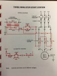
I would do it like this, but I noticed the m coil contact is located further away than any diagrams in used too. So I figured I'd ask
Sent from my iPhone using Tapatalk
I am not sure I understand what you mean.
BTW: Did you notice that in your first pic the start button was incorrect? It was NC instead of NO.
Instructor for the motor control class get it wrong?BTW: Did you notice that in your first pic the start button was incorrect? It was NC instead of NO.
I am not sure I understand what you mean.
BTW: Did you notice that in your first pic the start button was incorrect? It was NC instead of NO.
The normally open contact is usually how I see it in my second pic, but on the first pic it's located further away. So if I drew it how I'm used to.( like the second pic) It would just look odd to me.
Sent from my iPhone using Tapatalk
The normally open contact is usually how I see it in my second pic, but on the first pic it's located further away. So if I drew it how I'm used to.( like the second pic) It would just look odd to me.
Sent from my iPhone using Tapatalk
I'd have put the OLs upstream of the stop button.
I would do it like this, but I noticed the m coil contact is located further away than any diagrams in used too. So I figured I'd ask
Sent from my iPhone using Tapatalk
but physically, our NEMA starters are not wired that way, they are wired per our conventions, which is for the OL contacts to be on the right side of the coil, all by themselves.I'd have put the OLs upstream of the stop button.
That's fair enough.but physically, our NEMA starters are not wired that way, they are wired per our conventions, which is for the OL contacts to be on the right side of the coil, all by themselves.
I wouldn’t be happy with the O/L on the return leg. What would happen if there is a earth/ground fault on the return leg?
I suspect he meant what would happen if a ground fault occurred in the conductor between the overload contact and the M coil. It's a common enough observation when someone analyses the circuit that the overload contact will be shorted and there would be loss of overload protection. However, a physical observation of a common NEMA starter would indicate that the particular conductor in question is extremely short and a ground fault occurring on it is extremely unlikely. It is somewhat hinted at in Section 430.74 where a ground fault remote from the controller must not bypass safety shutdowns.Nothing. If you'll notice, the return is already grounded at the transformer secondary.
Sent from my iPhone using Tapatalk
I wouldn’t be happy with the O/L on the return leg. What would happen if there is a earth/ground fault on the return leg?
If you mean the right hand leg of the ladder diagram, it is shown as earthed at the transformer.I wouldn’t be happy with the O/L on the return leg. What would happen if there is a earth/ground fault on the return leg?
I don't recall ever seeing a small motor MCC with the O/L's on the "left" side of the M coil. They usually wire a motor overtemp contact or interlock there, but not the O/L's.
We built a majority of our own motor starter/control systems, and if we used a separately mounted (thermal or solid state) O/L block we always put the O/L contacts on the return (grounded) side of the 120V starter coil. Mainly because that's the way the factory wired ones were and we wanted to avoid confusion. Control wise, obviously, it makes no difference. I've never really thought much about why. Is it just an industry/NEMA standard?
but physically, our NEMA starters are not wired that way, they are wired per our conventions, which is for the OL contacts to be on the right side of the coil, all by themselves.
The OL contacts are shown incorrectly in that original picture too, they should be depicted as NC, not NC (assuming standard functionality). Whomever made that first picture was sloppy at best, possibly incompetent.