electrofelon
Senior Member
- Location
- Cherry Valley NY, Seattle, WA
- Occupation
- Electrician
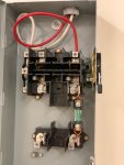
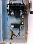
Saw something very odd the other day. Went to hook up two machines (something for biotech stuff, no idea what they do - I heard "magnet, isotope, inert gas...."). I think they were European in origin. Didnt have any documentation but the label said three phase, 230V +/- 10%. The machines were used and I did have some pictures of the previous installation. The way they were hooked up previously the three phases were all connected common to a single line. The machine takes a neutral as well. I assume either someone didnt have three phase and/or didnt know what they were doing. I assume all the machines components utilize line to neutral and there are no 220 or three phase loads since as far as I know the machines worked fine at their previous home. The machine is quite complicated and powers several other remote components so it was completely impractical for me to try and reverse engineer the thing. I had to make a decision about how to connect them. What would you have done? I ended up connecting them to a single phase, as they were previously. My thinking was there was a chance something had been modified or changed to be connected like that and that connecting it with separate phases was more likely to fry something due due to introducing 208 volts between conductors instead of 0.