
muckusmc
Senior Member
- Location
- Roebling, NJ
The inspectors here use a lighter to hold by the sensor to check to see if it is working. Fan comes on with the switch off.
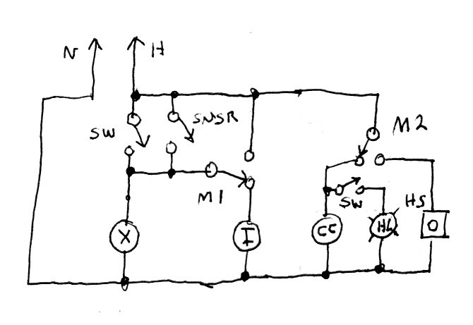
muckusmc said:HS = Horn Strobe - required here but check with AHJ as to location - some want the HS in the dining area - others in the kitchen.
muckusmc said:The inspectors here use a lighter to hold by the sensor to check to see if it is working. Fan comes on with the switch off.
That's why I use a single switch whenever I can, and I've come up with some creative ways.hillbilly1 said:Since there is usually only two micros in the ansul, the fire alarm contractor would love you for stealing his contact.
Now there's a diagram I can critique! (Nothing personal, Mr. Muck :smilemuckusmc said:
")
LarryFine said:Okay, I'm back. Dinner was great, thank you. :smile:
Now there's a diagram I can critique! (Nothing personal, Mr. Muck :smile
Why use a contactor for the fans? If they can share a single circuit (i.e., 120v and <20a), the micro's, usually rated at 16a, can handle the current. After all, the micro carries the exhaust-fan's current during system trip in your drawing.
Besides, the micro's will only switch under load when testing or in case of a fire, but not during daily use. Now, if either or both blowers are 240v, 3-phase, or use too much current, then you'll need a contactor or two anyway.
On the other hand, the receptacle(s) and any other electrical appliances should be switched by one or more contactors, and should never be on the same circuit as the system controls and hood lighting; that's a code basic.
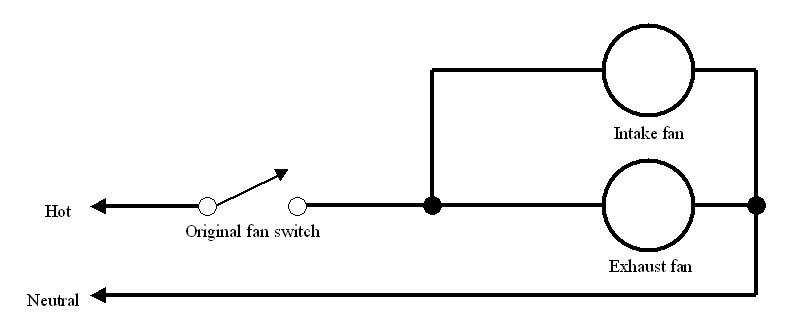
I drew up a couple of diagrams while I was eating. The first one basically funtions like the one Muck linked to, but no central contactor and a simpler circuit. The right half is the same as his linked image.
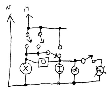
Then, if we really need to use only one micro-switch, as shown in the second drawing, it requires the concession that the fans must be on for the lights and appliances to function. This is required for electric gas valves here, by the way.
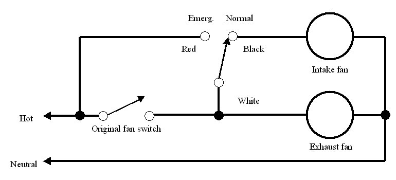
Notice that the horn/strobe is connected between the two blowers; the current required is miniscule. A gas-valve and its reset box would be connected across the intake fan (or its contactor) along with the appliance/receptacle contactor(s).
The SPDT switch directly above the intake fan (or its contactor) is the microswitch. When tripped, it removes the supply to the intake fan, the appliance/receptacle(s), and the light switch.dmanda24 said:on your second diagram, how is power cut off for the intake fan when the alarm is on?
Are you saying that 'critique' is not a verb? Would you prefer 'criticize'? :smile:Chamuit said:Critique = a discussion exercising or involving careful judgment or judicious evaluation.
LarryFine said:The SPDT switch directly above the intake fan (or its contactor) is the microswitch. When tripped, it removes the supply to the intake fan, the appliance/receptacle(s), and the light switch.
At the same time, it bypasses the sensor and manual fan switch, since it forms a parallel pathway. That's how I am able to use a single switch most of the time: remove power from one wire and feed it to another.
About the sensors mentioned: when they install systems here, the Ansul head has two cables, one for manual pulls, and the other under tension. There are lead links in the cable above the grease-catchers.
No. Since the strobe requires so little current, I'm supplying power to the strobe through the intake motor.dmanda24 said:but the strobe is connected to the intake fan so you are suplying power to the intake fan through the strobe. no?
LarryFine said:No. Since the strobe requires so little current, I'm supplying power to the strobe through the intake motor.
There's nothing that says one side of the strobe requires a directly-grounded conductor; it just needs 120v.
It's the only place there's a potential only during an alarm condition in the single-micro-switch diagram.