Cummins 20KW Generator low voltage wiring

MGRABHAM

Member
Location
Sherman, Texas
Occupation
Engineer
Hello,
Does anyone have a copy of the Cummins Onan ATS RSS200-6869 "Interconnection wiring diagram without controller 0630-3518"? If so, please attach. Thank you.
 

MGRABHAM

Member
Location
Sherman, Texas
Occupation
Engineer
All, what Cummins ATS do you typically install with a Cummins genset RS20AE?
Is it the RA212S3 model?
It's starting to look like my choice to use
the RSS200-6869 SE was a bad choice. None of the low voltage wiring configurations worked so far.
 

MGRABHAM

Member
Location
Sherman, Texas
Occupation
Engineer
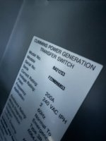
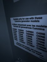
The Cummins generator is far superior to the Generac’s, but their wiring diagrams are the worst. They have started giving a cheat sheet that simplifies which diagram to use now. I tried to find it, but my truck is mess right now, so it is buried in it somewhere. Here is some pictures of the basic controls, if you are doing the load shedding, you will need more. This is for the service entrance rated switch. Don’t forget to remove the bond jumper in the switch if you are not using it as the service disconnect.
Hillbilly1,
Do you happen to know the transfer switch model from the pictures that you provide above? Thank you.
 

hillbilly1

Senior Member
Location
North Georgia mountains
Occupation
Owner/electrical contractor
Here’s the info on the last one I installed. I always order the package deal, I didn’t need the SE model on the last two installs, but it’s easier to get.
 

Attachments

  • IMG_1057.jpeg
    IMG_1057.jpeg
    1.5 MB · Views: 23
  • image.jpg
    image.jpg
    769.2 KB · Views: 22

hillbilly1

Senior Member
Location
North Georgia mountains
Occupation
Owner/electrical contractor
I would check K1 and K2. I had a bad K1 on a brand new 2000 amp transferswitch many years ago. Luckily the fire alarm guy had one on his truck, and we were able to commission it that night. Since it’s not starting the generator on power fail, I would look at K2, possibly welded contact, since it should fail closed. I’m assuming this was an existing switch with a new generator?
 

MGRABHAM

Member
Location
Sherman, Texas
Occupation
Engineer
Hillbilly1,
As you previous noted my RSS200SE has a battery charger in the panel that's connected. Also the RS20AE gender has another battery charger that's also connect. It is my opinion that I need to disconnect the ATS battery charger, do you agree. Therefore the ATS TB4-7 B+ is left open and not tied to the genset TB1-8.
 

MGRABHAM

Member
Location
Sherman, Texas
Occupation
Engineer
My previous comment is not correct. The RSS-200 ATS internal battery charger provides the 12v B+ and B- to the ATS TB4. Therefore if its remover/disabled the ATS TB4 needs to pick up the 12v B+ and B- from the GenSet TB1-7 B- and TB1-8 B+. Is that correct?
 

hillbilly1

Senior Member
Location
North Georgia mountains
Occupation
Owner/electrical contractor
You will need the B- for K1 to work, don’t think you will need B+ though, unless you have a remote annunciation. You can also just pull the fuse on the ATS charger to disable it.
 

MGRABHAM

Member
Location
Sherman, Texas
Occupation
Engineer
Hillbilly1,
Based on all of the communication and schematic diagram comparisons of the RA ATS Series vs. the old RSS200 ATS Series transfer switch this configuration should work;
RSS200 ATS; TB4-1 Utility Sense tied to GenSet TB1-6-STS-TB4-1 Remote Start input
RSS200 ATS; TB4-3 Transfer Switch Control tied to GenSet TB1-5 ATS Transfer Control
RSS200 ATS; TB4-3 B- tied to GenSet TB1-7 Ground
P.S. The Signal Pins TB4-3 & TB4-4 are tied together in the RSS200 ATS diagram, therefore no physical jumper is required.
I will give it a try this weekend. Once I have this config. setup I will also confirm that the voltage across TB4-1 to TB4-4 is 12vdc when utility power is ON and 0vdc when utility power is OFF. The only other choice if this does not work is to remove the RSS200 ATS and replace it with a RA212S3.
Thank you.
 

hillbilly1

Senior Member
Location
North Georgia mountains
Occupation
Owner/electrical contractor
Hillbilly1,
Based on all of the communication and schematic diagram comparisons of the RA ATS Series vs. the old RSS200 ATS Series transfer switch this configuration should work;
RSS200 ATS; TB4-1 Utility Sense tied to GenSet TB1-6-STS-TB4-1 Remote Start input
RSS200 ATS; TB4-3 Transfer Switch Control tied to GenSet TB1-5 ATS Transfer Control
RSS200 ATS; TB4-3 B- tied to GenSet TB1-7 Ground
P.S. The Signal Pins TB4-3 & TB4-4 are tied together in the RSS200 ATS diagram, therefore no physical jumper is required.
I will give it a try this weekend. Once I have this config. setup I will also confirm that the voltage across TB4-1 to TB4-4 is 12vdc when utility power is ON and 0vdc when utility power is OFF. The only other choice if this does not work is to remove the RSS200 ATS and replace it with a RA212S3.
Thank you.
Should work. I have taken cheap Generac transferswitches and re-wired them to work with a two wire start generator, but it is somewhat involved as you need timers to control start and transfer functions, the Cummins has that built in, just like Generac, but Generac has the utility sense built into the generator instead of the transferswitch, But from the input/output label you posted, it should work.
 
Top