Current loop resistance budget

That Man

Member
Location
California, United States
Occupation
Electrical Designer
I've been wondering this for a while. 4-20mA current loop. There's a definite limit to how many devices you can put in a loop, since each device has a resistance.

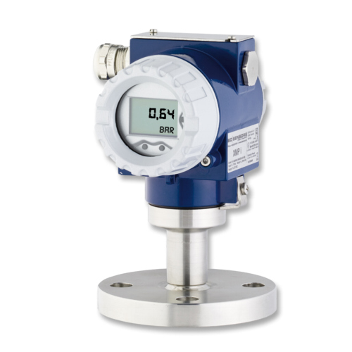
Lets say we have a 24V power supply, a 250 ohm device, and a 500 ohm device. One can be a PLC I/O point, another a transducer, it doesn't matter (I think). Can we add more devices? Pretty sure, based on simple ohm's law calc:

E=IR where E=24V, I = 20mA
24 = 0.02 * R
24/0.02 = R
R = 1200 ohms

Since our loop has 750 ohms of resistance, we have 450 ohms available for another device(s).

So I was wondering. Instead of adding another device, can we simply have a REALLY long circuit? Assuming 18AWG wire, that's about 21 ohms/km. double that since a circuit has to go there and back again, to 42 ohms/km. Does that mean a 4-20mA circuit can go 10.7km before resistance of the wire plus devices exceeds the resistance budget and the signal is no longer accurate? Does this also mean that to extend the range beyond this for some crazy reason, you can just use a larger power supply, like 48V?

Am I missing something? Are there other effects that limit a loop length? Are they calculate-able?
 
You can definitely calculate them. This seems completely theoretical. Please let me know if not.
What is the power rating of your supply? Find that then convert the power rating to source resistance. Then it is a simple voltage divider circuit (https://en.wikipedia.org/wiki/Voltage_divider). The voltage divides between the wire resistance, the source resistance, and the load resistance.

The circuit does not 'push out' a constant 24 V.... For 4-20mA current loop circuits, the current signal is varied based on the physical thing it represents (say shaft speed or something like that). This means the current changes based on the physical property, so the voltage is going to change as well.

When you start getting crazy long wires like this, just the noise in the line itself is going to equal or exceed your signal, so you would not be able to distinguish noise from signal. It starts behaving more like an antenna. To run really far distances at really low signal levels like that, you really have to start looking at the wire installation and type (line impedance, capacitance, shielding, etc...) because all of it starts to add up. Check out https://en.wikipedia.org/wiki/Signal-to-noise_ratio. Not to get too 'engineery' on you, I'd guess the induced noise in the wire would be at least 4mA without shielding it and doing a lot of stuff to harden it.

I thought 4-20mA loops were pretty old school now. Mostly I saw them in industrial controls and tight control loops, not for long distances. What's your application?
 
Back in the day, we used to use "DC remotes" for 2-way radio circuits to a base station located on a mountain or something.

This would travel over the telco's twisted pairs for many miles.

Both DC for control functions and the actual audio. The DC was 5.5 mA and the audio was just a weak audio signal like anything. Pickup of noise was never a problem if the line was in good condition, it would have wiped out the audio long before degrading the DC.

The power supplies I have seen could go well over 100 volts into an open circuit, by golly it was going to push that current no matter what.
 
Thanks for the reply!
This seems completely theoretical. Please let me know if not.
Yes, completely theoretical in this case.
I thought 4-20mA loops were pretty old school now. Mostly I saw them in industrial controls and tight control loops, not for long distances. What's your application?
Application is industrial controls :) It's just that sometimes, an instrument is thousands of cable feet away.

This has come up from time to time in the course of my career. How long can you run a 4-20mA signal? It;s been 20 years, and no one seems to know lol. Don't know why it took me this long to calculate it out, but it sounds like there ARE other factors in play that limit a circuit length.
Not to get too 'engineery' on you
No no, please get as engineery as you can. I want to have as thorough knowledge as possible so I feel comfortable speaking on topics like this.
 
Thanks, but... With respect, people do know how to figure this, but there are so many variables and factors that you have to account for and really do the hard math and testing, and this is not the forum to convey this. We live on the shoulders of Giants. People have done this for more than 100 years. Electrical engineers put in a lot of hard work to make things like this work.

I know this is theoretical, but this is something that you would need to engineer (plan, design, build, test, etc...) to ensure it all works right. This is not the forum to do it because it would need on-site analysis, a lot of figuring, and I think I have beat this to death...

Start with your power supply (is one way to start). It will only supply so much current at it's rated voltage. When this limit is exceeded, all bets are off. It may start cutting out, it may just burn up and die, it might limit the current, or it might limit the voltage to protect itself. Or, maybe it is fused. You have to account for the type of supply and how it reacts to limits being exceeded. To complicate it further, it also depends on what is supplying your power supply.

I am willing to take this 'offline' for deeper insight. Please message me if interested. Theory IS very good to know but I still like to stay in the 'real-world' where there is an application... What kind of application could you think of doing with this? Maybe look at https://en.wikipedia.org/wiki/Transatlantic_communications_cable.

Nowadays we harness the power of light for these things, since it is usually better and we know how to do it. I will get off my soapbox now :)
 
Top