Dealing with inspections on 30VDC home system.

Status
Not open for further replies.

fastline

Senior Member
Location
midwest usa
Occupation
Engineer
Per my other post about someone doing a tiny home, he has decided that a 24V system is probably the easiest thing to do, though I have never personally installed a 24V home system. This will be a solar system and we will be installing an outdoor charge controller so the entrance will be at 24V and there will be a battery indoors.
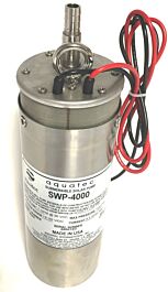
The two loads served is just a couple overhead lights, an exhaust fan for required air circulation in the space, and a water well pump.

I have not yet sized the pump yet but basically this is all minimal stuff. So far 100-250W but the issue is the pump is 200ft from the PV system. Though I know 24VDC motors are very tolerance of lower voltage from Vdrop, I have concerns we cannot get this bought off without some pretty serious and expensive wire!

Any thoughts or experiences with this?
 
Can you locate a battery and contactor closer to the pump so that the 200 ft. run would just need to keep the battery sufficiently charged over time, and not need to supply the full current level when the pump is running?
 
Thanks!
Synchro, while I do agree with that idea, it might create other issues. as the 200ft wire set would then be charging the battery bank near the well and the solar system will likely have more wattage potential than the well pump would need and would still have to size the wire set for that.

I was trying to determine if there was anything in code that provides additional acceptable voltage drop for low voltage loads? The issue is when you run a voltage drop calc, the actual reduction in volts is the same whether that is 12V or 500V. It is just that when you take 4V away from 12V, that value as a % is MUCH hire than at 500V. In automotive applications, it is just well accepted that due to the lower voltage, Vdrop is just accepted as normal.

Give me your opinions on this one guys. Due to the Vdrop issues here, and the fact that NEC low voltage standards seem to apply to 60V and less, I might propose trying to do a 48V nominal system as the max charging voltage would be 58.8V, and this would get me to just a touch over 10% Vdrop for the branch? I am not yet sure of any additional considerations going from 24V to 48V. Obviously switches and such will be more expensive but it seems futile as if we don't do this, the cost of wire will be substantial and I am proposing nothing larger than 12ga wire for this branch as that is pretty standard for a well pump system. It would be hard to obtain rated wire for a submersible pump at 8ga.

Only other way I see possible is as synchro mentioned and set a battery box near the pump, and let the 200ft of wire between the dwelling and pump serve as the charge wires, but I would also need to add signal wires for a contactor. Basically the mechanical pressure switch inside the structure would be firing the contactor. I know there has to be a smarter way, I just need to ponder this.

As well, if we use the 12ga branch wire set for charging, that could be considered a main feeder in which only 2% drop would be allowed?
 
So far 100-250W but the issue is the pump is 200ft from the PV system. Though I know 24VDC motors are very tolerance of lower voltage from Vdrop, I have concerns we cannot get this bought off without some pretty serious and expensive wire!

Any thoughts or experiences with this?
Good for you for taking this project on.
Allot of EC's run away from this kinda thing.
I have been developing a modular 120VDC system for this kinda thing.

Basic idea is semi portable;
Used (reconfigured) EV battery pack <- BMS <-120 VDC charge controller/rectifier <-PV input, generator or grid input
stackable modular battery banks to add AH

Then menu of output options are:
120 VDC -> 120 / 240 inverter for conventional loads
120VDC to pumps, motors or larger resistive loads
DC/DC converter for 12/24 DC loads and controls.
120 DC input VFD for 3 phase pump
 
How deep is the well?One relatively low current option I have seen for off grid is a mechanical pump with drive rod running from top of well to below water level (like the non-suction old fashioned lever pumps) and a motor/actuator to move the rod. Works well for low volume pumping with low power level and supports deep wells, but is pricey.

If you need a higher volume submersible pump (high minimum power requirement) then tortuga's VFD option makes sense. With an appropriate output filter you could run power to the well at high voltage (VFD output).
Grundfos makes a submersible pump with electronics to allow direct operation from solar without a battery. This will need a surface storage tank but supports 24V on-demand pump at point of use. Also very pricey.
 
Last edited:
Thanks!
Synchro, while I do agree with that idea, it might create other issues. as the 200ft wire set would then be charging the battery bank near the well and the solar system will likely have more wattage potential than the well pump would need and would still have to size the wire set for that.

Although it costs some money, one way to limit the current through the 200 ft wires when charging the battery (and also have accurate and responsive charging in spite of the higher wire resistance) is to have a DC/DC charger located at the battery near the well. For example, consider the model 24/24-12 charger at the links below:


The lower input voltage limit is 16V. And so it can still charge the battery even if there was an 8V drop from the 24V source through the 200 ft. wires, although you'd obviously want to avoid that much drop. If you just connected a battery at the well directly to the 200 ft. wires then the charging current would be determined by the voltage difference between the two batteries and the wire resistance via ohms law. And so there'd be an approximately exponential settling of the battery voltage which slows down more and more near the end. The DC/DC charger does not have this constraint and so it can charge and converge to the proper charge voltage more quickly and accurately.

They don't specify the maximum input current, but the output current is spec'd at 12A/15A/30A under continuous/max/short-circuit conditions. And so the input current of the 24V/24V converter drawn from the 200 ft. wires would not be much more than that under those conditions, which should alleviate your concerns about high charging currents through the wires.

Is there a possiblity of having the solar feed the charge controller and battery at a small "well house" instead of at the tiny home. Then the tiny home would be fed from there by the 200 ft. wires. If there was only a few hundred watt load at the timy home then perhaps the long wires could be smaller gauge.
 
Last edited:
I think my target on this is to keep it as simple as possible because the code guys will probably be scratching their head from the getgo. I realize setting solar at the pump is an option but then it will probably be more practical to dig a pit for the pressure tank because this area freezes. He is a bit resistant to having to make a pit since the dwelling will already have to be heated.

The actual minimum flowrate for water will be minimal as it I think my code just needs to handle the loads served. So probably only 2gpm, especially since it will be connected to a pressure tank which will basically be the pressurized rezzy for this. However, plumbing code required a minimum pressure of 15psi. It would be nice to find a DC pump that is high lift, low volume but they seem to only come in one flavor.

We did discuss the manual water pumping option but I think the permit guys will squawk at that. They already have scratched their head if no battery is provided because they are like "how do you get water when dark?" I do get that but I was selected because I have done this and actually lived on it! I am 100% certain it will work, but I also have to get this one signed off.

I am debating on just considering a 120V AC inverter for this. But I might look to you guys for code compliant thoughts?? If we enter the dwelling at anything beyond 30V, they are likely going to want the full roll out with load center, GFCIs, etc. This is all for 100sf??? lol But if I cannot solve the pump problem, we might be stumped and when you step to 48VDC gear, the price goes nuts! AC components are dirt cheap in comparison.

I have never had to look at "what are the absolute minimums" for a residential AC install. So far I know the entrance conductors must be rated to 100A. That is really not a big deal, but what else? So far it seems like putting any battery system outside in a plastic enclosure because NEC codes require vent considerations which is a real consideration for Hydrogen build up. They also require a corrosion proof enclosure so I think a plastic box would serve. It says nothing about a "rated enclosure"..
 
I am proposing nothing larger than 12ga wire for this branch as that is pretty standard for a well pump system. It would be hard to obtain rated wire for a submersible pump at 8ga.

Not true. I have sub pump cable up thru 4/0 for 125 hp submersible pump motors at my shop. In fact I don't even stock 12 ga pump wire. 10 ga or bigger. I buy it in 500 or 1,000 ft spools. I do have one pump distributor that has 3,000 ft spools and cuts to length.

There are also inwell pressure tanks.

How deep is the well? What is the water depth? What is the casing diameter? What is the desired flow rate and at what psi?
 
I work with water wells quite a bit and have worked with this guy to fully test the well performance. She is 120ft deep with static level at about 25ft. But drawdown is significant and this well can only produce 12gpm but test pump was only set at 90ft. By my estimation, drawdown will probably be to 50ft. We will need approx 2gpm to serve this need right now. the 15psi min is 35ft of head plus the 50 on the well, so I need a min of 85ft of head. I realize I will need to observe the pump curve to ensure the pump can have headroom to get the job done. Realistically, we will need more because I will have to set the pressure switch to 15psi cut in so cutout will of course be higher.

The well is a 5" PVC cased well.

The pressure tank is either a 20 or 30 gal. can't recall. Std shower heads are about 2-2.5gpm but that is at 40psi. I would estimated about 1gpm on the shower which RVs run on all the time without issue. My estimated water needs are about 20-40gpd, so that pump will only run a couple x/day.

I intend to looks closer at the Ah or watt hr requirements here to ensure there are days of use on reserve. As well, a solar PV system absolutely can make power even in the rain, though substantially limited. Lead acid is never my best choice but probably practical here. I will determine any derates for temperature, current, etc, but I tend to doubt the inspectors will be all up on that so I won't submit that unless requested. Basically lead acid Ah is based on a 20hr rate and at full discharge. You never discharge beyond 50% so that is factored immediately. Then factors for any current beyond the 20hr rate but I don't think that will apply since the pump will only run for minutes and any LED lighting loads will be very minimal. Probably 30-50W
 
Last edited:
Synchro, while I do agree with that idea, it might create other issues. as the 200ft wire set would then be charging the battery bank near the well and the solar system will likely have more wattage potential than the well pump would need and would still have to size the wire set for that.
Main battery bank and solar can still be by the house, but you could add a dedicated battery at the well pump. That way the long run only has to carry the average current required by the pump (plus battery round trip losses), not the peak current required by the pump.

Cheers, Wayne
 
Ill second Syncros idea.
Re the inside wiring:
If we enter the dwelling at anything beyond 30V..
To keep within 720.1 I believe its 50 volts or less.
Take a look at 720.7, I doubt you'll need much.
If cost was not a issue you could bump it to a 24/48V 3 wire system and have both 24 (for lights) and 48VDC for the pump.
 
Main battery bank and solar can still be by the house, but you could add a dedicated battery at the well pump. That way the long run only has to carry the average current required by the pump (plus battery round trip losses), not the peak current required by the pump.

Cheers, Wayne

I am not quite following what you propose. Could you explain further? If a battery is parallel connected to the pump and branch wires, the pump would run all the time. If there is a battery out there, it would need to receive charging and have some means of conductor ampacity.

I am really trying to find codes that apply to this. so far I have found art 411 for low voltage lighting indicating a 60VDC max.
 
Here is where I am. See if you guys agree. I might have a workable path. Conductor Vdrop per the NEC is a "recommendation". This accounts for many utilities having a voltage tolerance delivered at +/- 10%, or that is at least what it is here.

The reality is a 24V 'nominal" voltage should never be 24V. Full charged voltage should be 25.4-25.6. Actual float voltage will of course be higher. Fully discharged batteries to 50% charge is 24.4V. But if I were to consider the full 10% voltage drop as would be in utility power, that is less than 23V, in which that is considered battery damage territory.

I am thinking we have a little more wiggle with the Vdrop on such a low voltage system, but I also don't need any drama from an inspector on a piddly job.
 
Can you locate a battery and contactor closer to the pump so that the 200 ft. run would just need to keep the battery sufficiently charged over time, and not need to supply the full current level when the pump is running?
Main battery bank and solar can still be by the house, but you could add a dedicated battery at the well pump. That way the long run only has to carry the average current required by the pump (plus battery round trip losses), not the peak current required by the pump.
I am not quite following what you propose. Could you explain further? If a battery is parallel connected to the pump and branch wires, the pump would run all the time. If there is a battery out there, it would need to receive charging and have some means of conductor ampacity.
I think Wayne, Tortuga, and I are on the same page on the idea under consideration. The extra battery near the pump would be connected to the pump through a contactor and not directly to the pump. As you mentioned above in post #4, a pair of control wires would go from a pressure switch near the pressure tank (inside of the house) over to the contactor by the pump to activate its coil and turn on the pump. And so the extra battery would only be connected to the pump when this contactor is closed. There would be a separate connection to the extra battery for charging it using the power supplied through the 200 ft. run.

Since my post #7, I thought of a few other reasons for having a DC/DC charger connected to the extra battery which is fed by the 200 ft. run, instead of directly connecting the two batteries with this run. The charger would allow the state of charge (SoC) of the battery inside the tiny house to be independent of the SoC of the extra battery near the pump. Having the 200 ft wires connect the battery in the tiny house directly to an extra one near the well pump would not allow this independence.

Some issues with a direct connection (in addition to the ones I mentioned in post #7) are:
If both batteries are heavily depleted but now there's plenty of solar power to charge them, then charging the battery in the house at a high rate may elevate the voltage on this battery enough to produce a relatively high current though the 200 ft. run. The ampacity of this run would then have to support this higher current instead of the average current drawn by the pump over a relatively longer time period. The charger would eliminate this constraint.
Similarly, even if you draw down the battery in the house to say the 50% level, then a DC/DC charger could still maintain the charge on the extra battery at a higher level than 50%. This could be helpful because if the pump is activated and draws its high current in this situation, then this higher SoC it makes it less likely that the charge on the extra battery would be pulled down below the acceptable level.
 
Did I miss it or did you not say anything about the pump you intend to use? Might look at the aquatech SWP-4000. It will run in 12-24 volts so just give it 24 and whatever loss there is big deal. Just to allay you concerns a bit, I have a 12V "RV type" pump (fed with about 13.5V) 600 feet away with #6AL wire. Its been working for years. Some overthinking going on .
 
Did I miss it or did you not say anything about the pump you intend to use? Might look at the aquatech SWP-4000. It will run in 12-24 volts so just give it 24 and whatever loss there is big deal. Just to allay you concerns a bit, I have a 12V "RV type" pump (fed with about 13.5V) 600 feet away with #6AL wire. Its been working for years. Some overthinking going on .
I'd like to get more details!! Like what is the power requirement for that DC pump? I have one and they pull next to nothing I believe. They are a diaphragm pump usually. If you know the current or any other parameters, it would sure help! Thanks!

As I mentioned, I have sort of concluded that no inspector can really balk at Vdrop here because the power is essentially free so it just comes down to "will it work". A DC motor will reduce in performance a bit, but near impossible to kill being in a pool of cold water.

But I certainly do appreciate the out-of-box thinking on this guys! I think I have more concerns of the pump actually performing on mark. If it cannot achieve the proper head pressure, it will just run continuously. I intend to put a toggle switch on the pump so it can be left off when not occupied.

I think my plan is viable. Just wish that pump was closer.....lol That would solve all of these issues. Or if it was not for the code guy, I would just throw an AC inverter in, pitch a 1/3hp AC 240V pump in, and problem solved....
 
Bam, I think we have a path forward! I found a different pump that is a high lift/low flow and I found performance tables. Even pushing up to 230ft of head. At our head, it appears at least 2gpm will be no problem.
 
Status
Not open for further replies.
Top