Delta / Wye vs. GFCI

Status
Not open for further replies.
Re: Delta / Wye vs. GFCI

laidman,
If that were the case and there could be no fault current why can you install a GFCI on an ungrounded system and have it operate properly and trip.
Have you ever seen a GFCI trip on an ungrounded system? When we install GFCIs on two-wire systems, we are not installing them on an unground system, just one with out an equipment grounding conductor. The two wire system is a grounded system and there is a current path.
Don
 
Re: Delta / Wye vs. GFCI

laidman
I disagree. If the secondary of the transformer is not tied to ground there will be so little current flowing that there will be no chance for the GFCI to operate. The only current flowing will be based on the capacitance between phase and ground, and in almost all cases like this, the current will be zero.
People commonly believe that currents are trying to get to ground, and that is not the case.
Jim T
 
Re: Delta / Wye vs. GFCI

Originally posted by laidman:
If that were the case and there could be no fault current why can you install a GFCI on an ungrounded system and have it operate properly and trip.
Residential is not served by ungrounded systems. Ungrounded systems are only used by industrial applications where trained personnel are on site.

I assume you mean a two-wire receptacle withoout a equipment ground conductor. The system is grounded, just no EGC ran with circuit conductors. That is why the NEC requires a GFCI recept to be used for additions to these systems. Without a grounded system the GFCI would not work.
 
Re: Delta / Wye vs. GFCI

Here we go:

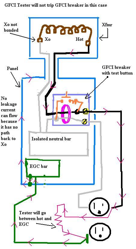
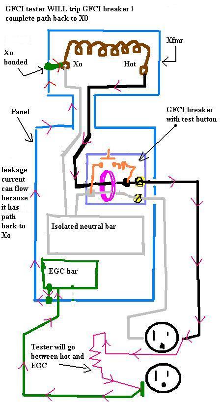
In both diagrams, the other phases in the xfmr and panel have been omitted for simplicity of drawing.

In the first drawing the tester plugged into the receptacle will not trip the GFCI breaker because there is no complete path for leakage current to flow back to the other side of its source = Xo

In the second drawing, with Xo bonded, there is a complete path for leakage current through the tester and the breaker trips.

I do not feel there would be enough capacitance to cause a trip in the first drawing.

The push-to-test at the breaker routes current around the CT in the breaker and it will still cuase a trip because the neutral (**grounded conductor... oops, not a grounded conductor or a neutral in this drawing!) in the breaker IS connected to Xo

Also, we often look at AC current flow as if it were DC, but it is really alternating directions. Just simpler to show one direction.

GFCI_no_trip.jpg


GFCI__trip.jpg


[ January 06, 2005, 04:31 PM: Message edited by: crossman ]
 
Re: Delta / Wye vs. GFCI

P.S. there may be some EGCs omitted in the above drawinfs, like from the xfmr case to the panel case, but this in no way affects the outcome if Xo is truely not bonded.
 
Re: Delta / Wye vs. GFCI

Originally posted by crossman:
P.S. there may be some EGCs omitted in the above drawinfs, like from the xfmr case to the panel case, but this in no way affects the outcome if Xo is truely not bonded.
Right. A proper 250.30 (A)(4) connection will make no difference because the impedance all the way back to the source will be far too high to allow the plug-in tester to trip the GFCI.
 
Re: Delta / Wye vs. GFCI

Peter D,

I have a couple of websites, one was for a project my daughter was doing, and another is a bike racing forum that I started.
 
Re: Delta / Wye vs. GFCI

peter d,
a trick to find out where the picture is stored is to Right Click on the picture and then click on 'Properties'.
It will then show you the web address of where the picture is located.
 
Re: Delta / Wye vs. GFCI

Thank you sir. I still have a big cylinder of helium left and about 200 more troopers to be sent off... just haven't done it. I haven't updated the site in awhile, but one of the troopers was recovered in Mississipi! About 400 miles away, they emailed us and sent the trooper back in the mail.
 
Status
Not open for further replies.
Top