You are using an out of date browser. It may not display this or other websites correctly.
You should upgrade or use an alternative browser.
You should upgrade or use an alternative browser.
Drive Question (Square D ATV 71)
- Thread starter C3PO
- Start date
- Status
- Not open for further replies.
- Location
- San Francisco Bay Area, CA, USA
- Occupation
- Electrical Engineer
"5pts" sounds as though this is a homework assignment and they want you to list 5 points that are difeferent from each other, is that right?Can somebody explain to me what the difference is in the motor control type SVC V and V/F 5pts and the different reasons, situations that you would use one or the other? Thanks in advance!
"5pts" sounds as though this is a homework assignment and they want you to list 5 points that are difeferent from each other, is that right?
I am not in school, I was having some drive issues and was hoping for more information then just what the program manual says about the two different settings. Here are screen shots of the two settings I am asking about.
Attachments
- Location
- San Francisco Bay Area, CA, USA
- Occupation
- Electrical Engineer
Sorry, should have checked your profile first, doesn't look like you are a student trying to scam free homework help. By the time I had finished editing this though, it had timed out.
SVC is Sensorless Vector Control. V/F is simple Volts-per-Hertz control. No idea what you mean by the rest to be honest, but the French tend to want to describe things on their own terms a lot, rather than stick to industry common terminology. So who knows.
With a VFD, at the very least the voltage and frequency must change together at an appropriate ratio to maintain torque in the motor at "any" speed command. But in that basic form, referred to as Volt-per-Hertz V/H or V/F for Frequency) or also "Scalar" mode, the VFD puts it out, but the motor may or may not respond properly or optimally based on the load and the response of the load to the change. So especially at lower speeds, the VFD may be telling the motor to spin at 25% speed, but the LOAD on the motor is only allowing it to spin at 20% speed. The motor would normally respond by increasing current, but the VFD may end up not allowing that to happen, so you end up with am "error" between the commanded speed and the actual speed.
Like in other feedback loop systems, you can read the error, and correct the response to reduce or eliminate it. A "Vector" drive does just that, it looks at the commanded speed, uses a feedback loop to determine the ACTUAL speed, then tweaks the output switching pattern of the VFD PWM signal to correct that error. In a Closed Loop Vector drive, that feedback is going to come from a shaft encoder on the motor, that reports back the actual motor rotor position to a high speed processor in the drive. An SVC version, dubbed as "Sensorless" is actually a misnomer, because the sensors are still there, they are just not external to the drive, such as the encoder. In an SVC drive, the electronics look at very small changes in current caused by the motor magnetics as the rotor passed through the magnetic fields of the stator. It holds a mathematical "model" of the motor's normal profile and compares these tiny changes to that model to derive the real rotor speed. So from that, it then makes those tweaks to the output to correct the speed (or torque) error that it sees.
Bottom line, a drive using SVC can be an order of magnitude more accurate in speed control, but perhaps more importantly, it can provide the correct amount of torque to maintain accurate speed control with widely varying changes in the load, and right down to NEARLY stopped rotors. The general rule is that V/F mode can allow relatively accurate speed control down to a 4:1 speed range, where SVC can maintain it down to 100:1, sometimes as much as 1000:1 on the better ones. So if you need to run a motor at 1Hz, you need SVC. If you are never going to run it below 50% speed, maybe not. SVC is great for things like machine tools and conveyors, but is relatively pointless on things like pumps and fans.
- Location
- Wisconsin
- Occupation
- PE (Retired) - Power Systems
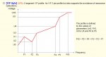
The 5pts in the attachment are simply showing that the V/F adjustment is not a straight line from minimum to maximum, but rather can have up to 5 different break points, or slopes.
- Location
- San Francisco Bay Area, CA, USA
- Occupation
- Electrical Engineer
OK, crossed in the ether, sorry.I am not in school, I was having some drive issues and was hoping for more information then just what the program manual says about the two different settings. Here are screen shots of the two settings I am asking about.
Looks like this is just a manual tweak of the V/F option, just in case there is some sort of mechanical harmonic that you need to avoid. Most other drives instead provide an option called "Critical Frequency Lockout" (or similar wording) instead, which just allows you to tell the drive to NEVER run at any mechanical harmonic you discover, and program the drive as to how you want it to respond, i.e. hold below or above, or immediately pass through a programmed bandwidth. This "5 points" option seems a lot more complicated if you ask me, but then I think the ATV71 is way over complex to start with so I'm not surprised.
weressl
Esteemed Member
I am not in school, I was having some drive issues and was hoping for more information then just what the program manual says about the two different settings. Here are screen shots of the two settings I am asking about.
One of the main use of the 5pt V/F control is to allow custom shaping due to non-linear or nonquadratic load torque charactersitics. I am sure they do have a setting for standrard centrifugal load such as blower, pump, agitator, but if not you can 'build' an appoximated cubed curve with this drive too. (I have investigated the Altivar drive in depth years ago against 5 other products when I was standardizing our drives and it kind of fell out of favor with me so my knowledge is not current with those, hence my comments are generic.)
We encountered a fan application - was a larger 5kV drive - where the complex ductwork shape, baffles, resonant frequencies and varying flow demands made it so that after setting the original cubed curve we were experiencing all sort of mechanical, flow and current problems. By slight adjustments on the slope in several places we were able to smoothen the operation in all of the troubled fields and spots.
Great comments from Jraef as always.
mike_kilroy
Senior Member
- Location
- United States
in addition to above, we've used the 5 point concept in v/hz drives to reduce internal resonance in machine tool spindle motors at certain low speeds where they would self resonate unless over magnetized (higher than normal v/hz), and others to way undervolts them from 0 to say 3hz to prevent short circuit overcurrent problems until the motor started rotating and stopped looking like a short circuit.
- Location
- San Francisco Bay Area, CA, USA
- Occupation
- Electrical Engineer
Yes, if the drive is not tuned to the motor. SVC, being dependent upon modeling the motor mathematically, must know what the motor characteristics are. You can program them in manually if you know all of the intimate details of the motor (very difficult to get sometimes), but most will do an autotune function, where you run the motor uncoupled for a few minutes and the drive runs it through some paces to establish the model. Did you do an autotune?Thank you everyone for the great answers. Have any of you encountered issues where a drive set to SVC would cause grinding noises and excessive vibrations in the application but when changed to V/F it runs smooth?
- Status
- Not open for further replies.