Earth Shells Experiment = time to eat crow!

Status
Not open for further replies.
I don't see then why the voltage drops are different at the stakes farther away from the deeper "energized" rod, since all the stakes should have the same "small connection point" resistance

I understand what you are saying.

The difference in my mind is that there is no significant current flowing in the test pipes, and therefore there is no significant voltage drop created in the the test pipe/earth contact area.

To put it another way: The 6 amp current is flowing from the hot wire to the pipe electrode, through its earth shells, and then through the earth back to the building electrode. The only current flowing in the test pipes/earth contact area was the current to operate the digital meter. And this very small current caused only a very very small voltage drop in the test pipe/earth contact area.

Keep in mind that the voltage drops I measured were real - the 33 volts from the electrode to the 1st pipe at 33 volts lit up a 24 volt lamp.

Seems to me there is an 8.33 ohm impedance somewhere that is limiting the current flow to 6 amp. Or else the power supply itself, whatever it is, is limiting the current flow.

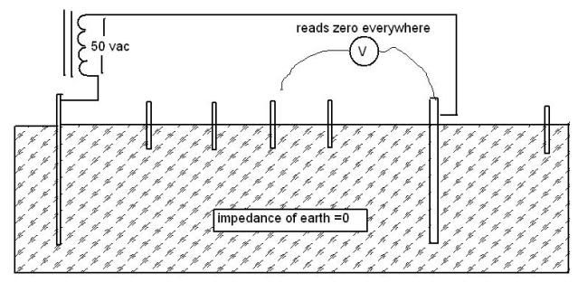
If the earth were zero impedance and there was a resistance between the earth and the stakes which was in series with the hign impedance meter, you should read zero on the meter and the 24v (incandescent?) lamp should not have lit.

this should be similar to measuring the voltage along a piece of wire using small resistances in series with the high impedance meter.

I don't see how if the earth is zero impedance, you would read anything.

Additionally how do you have your power supply (transformer?) hooked up on the supply end?

I don't see any way to conclude from your test that the earth has zero impedance... just the opposite.
And I don't see why the stakes farther from the other end of the power supply than the pipe would have any reading on them at all
 
Last edited:
I have no dispute with your experiment except the conclusion that the earth has zero ohms impedance
ZERO_IMP.jpg
 
Realoman:

Thank you for the discussion. When it is said that the earth has zero impedance, it has to be taken in context.

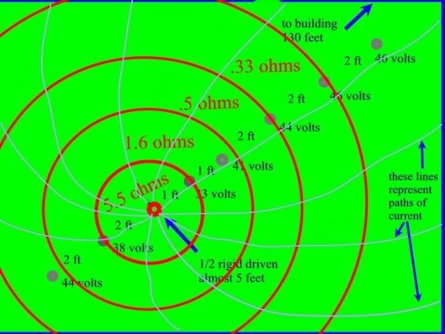
In the first diagram below, I added in the resistance values in the "shells" around the pipe. I also drew in some curent flow paths for illustration. The point is that the "circular mil area" of the shells increases as we move away from the pipe. Close to the pipe, we have fewer "parallel paths" then we do as we move away from the pipe. I hope my diagram will convey that.

The point is that small samples of the earth do not have zero impedance. The small sample with limited parallel paths will have a substantial resistance as evidenced by the voltage drop near the pipe. When we examine the current flow at places further away from the pipe, the current has a huge number of parallel paths to choose from, and as we know, parallel paths reduce the resistance.

Based on the above, in the shells far away from the pipe, the resistance is practically zero (not quite zero, but very close.) This was evidenced by the two test pipes that are furthest away from the electrode. Notice that the voltage drop was essentially 46 volts on either of these pipes. That means we had reached the point where the earth had a neglible resistance in relation to the electrode.

0diaa.jpg


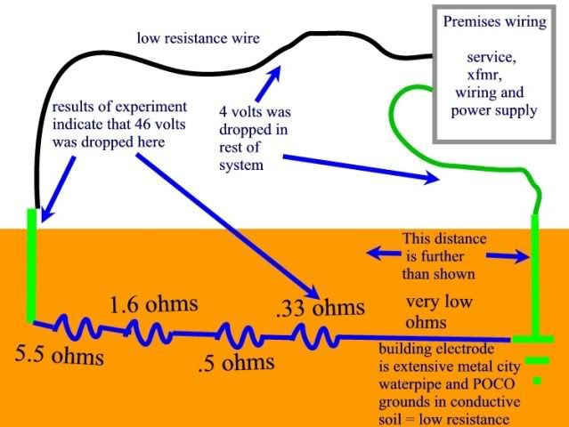
The diagram below shows a rough circuit equivalent of the experiment. Again, small pieces of earth around the electrode have a significant resistance. Further away where we are using big chunks of earth as the conductor, the resistance drops off to near zero.

00diab.jpg


A good point to bring up is "why didn't the building electrode have the same thing happening in the shells around it, and the voltage drop should be split between the electrodes?

My answer to that is the building has a huge grounding electrode system. It is no a "point" system like the pipe I was using in the experiment. There are miles of steel waterpipe, there is the POCO grounding system for the secondary of their xfmrs, there are underground rigid pipes for the service into the building which essentially act as electrodes, and there are smaller rigid conduits going to site lighting around the building. Even the electrodes in other buidlings around us may be playing a part because they are all connected together via the POCO ground. So, the earth shells around the building electrodes are huge huge in comparison with the experiment electrode.

I am pretty much convinced of all this now. In the past, I wasn't. I am still open to any discussion or other views. If the above doesn't help, let me know.
 
One other comment:

Say we have two huge metal plates, say 10 feet tall, 200 feet wide, and 1/2" thick.

I am in a football field in Houston, Texas. The soil is the typical black clay found in this area and is typically moist.

I dig a 12 foot deep, 200 foot long trench on one of the goal lines. I do the same thing at the other goal line.

I place the metal plates in these trenchs and compact the soil around them.

I measure the resistance from one plate to the other. I am betting the resistance would be close to zero.

My point is that the type of electrode and the contact area between it and the soil is going to have a huge influence on the shells and the resistance of those shells. (This is pretty obvious?)
 
I have no dispute with your experiment except the conclusion that the earth has zero ohms impedance
ZERO_IMP.jpg


OK I will try to explain this but first you must think in 3 dimensions not 2,

if you look at the chart I posted in post 11 you will see that as you get to the 0.6M mark the resistance curve starts flatting out, this is because your are reaching the edge of the SOI, of the rod, or the sphere of influence, the resistance of earth is being lowered by more and more soil around the area as a whole in 3 dimensions.

We don't have just the path between the rods but many paths through the earth, remember current takes all paths, resistance is the sum of all paths, and the farther out we get the bigger the sphere of these paths get, like getting a bigger and bigger conductor proportionally to the distance from the rod, its not the earth that has the high resistance but the fact we are making such a small connection to it, if we look at the quote in post 11 it explains this.

I will try to find the papers on the 500kvdc SWER transmission line that also proves this point.

It was a several hundred mile run with only one wire, and when all the losses were accounted for, it was summed up in just the line and the earthing electrodes.
 
0diaa.jpg


Please also note that in gary's test at the 4' mark, the voltage drop was equal in both directions, 44 volts, and I'm sure if he had done a 6' and an 8' point in the other direction this would have held true.

the only time the earthing of other metallic paths will influence this is if these pathways are within the sphere of influence of the injection rod, as we see they are not by the equal voltage drop at 4'

the difference of the 2' can be accounted for in the soil as the amount of earth is so small, but as we get farther out we will see a equilibrium as the distance grows, and since the flow of current is equal in all directions from the rod, the current is not trying to flow back to some single point but it is using the earth in all directions to flow back to the source.

This means it flows not only horizontal, but down into the earth also.

Think of the 3 dimension SOI like this: Place a 3' diameter bowl with your rod in the center, now stretch it down till even the bottom of the bowl maintains the same 3' from the rod, this is the shape of the sphere of influence of this rod, a horizontal rod would have a shape that looks like a long air tank with round ends at the ends of the rod, but at any distance from the rod it is 3'.
 
A good point to bring up is "why didn't the building electrode have the same thing happening in the shells around it, and the voltage drop should be split between the electrodes?
Simple your not injecting current at the building, and the reference is only the same as you did with a high impedance DVM, since there is no fair amount of current on the building electrode system in relation with the injected rod, there is no voltage drop across it


another thing I see is the total of the resistance in Gary's experiment was 8.26 ohm's if we subtract the figured resistance of 8.33 we get .07 ohms for the remainder of the pathway back to source, I'm sure if we were to get to the 100% mark shell we will find we still have a large amount of soil still between it and the source which would leave the only conclusion that Earth is in fact 0 ohm over all.
 
Last edited:
Skip the first part in my prevous post, as current shuld be equal on both systems, but like Gary said it has more connections points to earth and the current is divided across all these paths, so the eletrode system at the building will have very little current on it, so very little voltage drop from it.
 
090802-1259 EST

crossman gary:

A minor comment on your field map of post #27. You are drawing current flux lines from the rod to some destination to the north east. With this type of current flow the equipotential lines will not be circles, but rather distorted circles.

To hand sketch the filed map you need to sketch curvilinear squares where the corners intersect at right angles. A. D. Moore spent a half semester trying to gets his students to be reasonably proficient in this sketching activity. His technique used a circle guide as an assist. He also had developed an analog technique using liquid flow and plaster molds to create field maps prior to the existence of analog or digital computers.

A sample field map can be seen at
http://books.google.com/books?id=bC...esult&ct=result&resnum=9#v=onepage&q=&f=false

On page 25 of the document and 26 in frame count of
http://deepblue.lib.umich.edu/bitstream/2027.42/6682/5/bad0328.0001.001.pdf
notice how the flux lines intersect perpendicular to the potential lines.

.

But gar the field of current around a rod is equal in all directions, again this is the vary assumption that the current only travels in a straight line back to source, we see this in the two 4' measurements, of 44 volts, it wouldn't matter if he had taken measurements all the way around the rod, at 4' it will be the same, closer to the rod the soil composition can play a role in it, but as we get farther out measurements around the rod will be equal in all directions, as in a circle.

If we understand the 0 ohms resistance of the Earth as a whole, then draw a circle around a rod lets say about at the 12' mark, then put a reference voltage of 0 volts anywhere outside of this circle we can see why the current is equally flowing out-wards from the rod toward this 0 volts reference.

The current flow after it leaves the sphere of influence will take what ever path back to source, but it will take all paths back at 0 ohms, meaning it will be proportional to the resistance of those paths, at 0 ohms it will flow in all directions back to the transformer.
 
Gar, in your post in the other thread you made a statement of changing the direction of your two probes and found a different reading, ok let me use the analogy of a radio transmitter (rod), and a receiver(transformer).

We can use your two probes like this to find the direction of the transmitter, but in reality the transmitter (rod) is sending the signal out in all directions is it not, so in reality I can put the receiver 360 degs around the transmitter and at the same distance it will receive the same level of signal. so the signal is being generated 360 degs around the vertical dipole of the antenna, the same as the rod, but takes all paths back to the receiver, but if I go to the 90 deg point I still have the same level of signal.
 
090802-1441 EST

hurk27:

I do not believe the current source for the stray currents is in my yard nor originates very close to me. This of course is unknown at this time. A major problem is that the detector is moderately wide band, Fluke 27 with no filtering, and I have no phase information.

On the basis of this assumption my measurements are not like going around a monopole. Rather I am going around a long horizontal rod. Without phase information and simultaneous readings I do not know if I am simply an obstruction in the general path of a river, or the destination of all the water in the river.

If we assumed the stray current source was fairly remote and I was in the middle of a farm field with no conductors in the field, then as I moved around the field I would expect the current vector direction to remain constant.

In the case of my home I have this long copper rod (water pipe) that can act as a sink for stray current that is entering the yard.

My logic of what I think may be happening does not hold up in the backyard. This is confusing. But there is somewhat closer proximity of other ground rods at homes to my east.

The two screwdriver method allows one to get some idea of what is happening, but my suggestion of an octagonal, or more, array of probes, and automatic measurement would provide more useful results.

.
 
with using radio detection theory it is possible to always get one of two directions to the source, placing the screw drivers in phase with the source will show you the plane of direction and using a current coil will show you which of the two directions it is coming from (rule of the thumb) in current flow. objects in between can cause it to deflect but after you pass these objects it will Aline again with the real direction. this is the same theory used in the loop direction finder we used to find a radio transmitter.

The problem with Earth is unlike the air around us is it has a much lower impedance, more akin to standing on the opposite end of the globe from the transmitter, and trying to find the direction of the transmitter which would read equal in all directions.

but back on track, the fact that earth has 0 ohms outside of our connection point presents a problem as to all the paths the current will take, within the connection point, we call the SOI, it will take all paths to the 0 reference point of the earth that surrounds our connection point, this means unless another path exist that is with in the SOI of the rod, this will be in a all equal direction away from the rod not just in two dimensions but in three, out, and down equally all around the rod in a shape like a bowl elongated to the shape of the rod, so that all points between the rod and this bowl are of equal distance.
 
Gar:In the case of my home I have this long copper rod (water pipe) that can act as a sink for stray current that is entering the yard.

if the water pipe is sinking the current from this stray source, it has to be because it is also the return path for this source?

now you have stated that you have a delta primary, but you fail to relize that this delta primary is also connected to each and every transformer that also is connected to this water pipe, now on the pole there should be a MGN conductor, that is also a parallel path with this water pipe.

so one could imply that any loads upon the common ground (water pipe/MGN) your service point will also place a current upon this common ground, lets say the house next door, has lost it's neutral connection to the transformer, and now returns current through the water pipe, back through the service neutral of a house on the other side of you to the neutral at the transformer which is connected to the MGN, then back to its transformer.
you now have current traveling upon the water pipe and the MGN run down the poles.
 
Gary,
Again a nice job. This points out exactly why grounding does not really provide protection from a shock hazard(unless, as in your earlier experiments, the grounding path causes the OCPD to open the circuit). In the past it was a common practice here in Illinois not to use an EGC for any traffic signal equipment. A driven rod was used in an attempt to provide shock protection. A couple of lawsuits and a grounding seminar from Mike Holt resulted in the IDOT specs being rewritten to require an EGC for traffic signal equipment.
 
I have been watching this thread, and the others with great interest. Good stuff Gary. Check out these videos. AB Chance has a facility where they do similar experiments, but with about 10,000 times the power. I have visited this facility for some testing in Centrillia, MO in the past, very cool stuff. Watch the videos you can download, the tests where they put 40,000A into a ground rod are my favorites, watching the earth move in MO in the dead of winter is amazing. http://www.hubbellpowersystems.com/powertest/video/video_lib.html#
 
Status
Not open for further replies.
Top