Elevator Pre-Signal/ATS Question

Status
Not open for further replies.

JasonCo

Senior Member
Location
Houston, Texas
So my company doesn't do much motor control work but fairly soon they're giving me a job that deals with an ATS and a elevator pre-signal. The elevator technician will be on site but I'd really like to do the homework and go in with some confidence. Plus I'm one year into being a J-man and this would be a great opportunity to soak in some valuable knowledge.

My boss gave me a brief rundown of what's going on, and showed me a couple pictures. So it looks like the elevator technician has run 2 sets of #12 THHN conductors from elevator controller to ATS. I'm assuming they are 2 sets of dry contacts. From the homework I have done so far, and from the brief rundown from boss man, one set of contacts will be NC and will open once Emergency kicks in. The other set is NO and closes for pre-signal.

They have no idea if this ATS has a pre-signal or not, it is my job to troubleshoot this and achieve landing both sets of dry contacts coming from the elevator controller. If I have to add timing relays and what not, then I guess I'll have to.

For the NC contact to open on Emergency. I could add a single phase transformer and run line side off Emergency power and load side will go to a relay coil. Then my dry contacts coming from elevator controller will go on a set of NC contacts off the relay?

For the NO contact that closes for Pre-Signal, this might be a very dumb question but based off the picture, would anyone think I can achieve this or where do you think I should start looking for it if the ATS has a pre-signal. In my understanding, it needs to tell the elevator control room when normal power is restored so it'll give the cars enough time to stop motion before transferring back over to Normal Power. If this ATS doesn't have a pre-signal, how would you go about achieving this?

Thanks for all your time and help, looking forward to learning more about this.

Here is a really crappy picture of the ATS that they sent me:

 
Hi Jason
This may be a walk in the park if what I see in the pics show that you may already have the pre-signal (Westinghouse calls it pre-transfer signal) option already installed on this ATS. If you look at the top pic there is an Agastat timer and plug in Idec cube relay. If you verify the terminal and wire numbers to match the wiring diagram I have attached it may be as simple as wiring the pre-signal field wires (NO contact) from the elevator controller to the terminal block and wire the NC switch position contact to the relay that you would add mentioned above.
If this wiring is not there then you could build a module of a timer/ relay module like the one I made 7 yrs ago for a job to add this option. I have attached a reply to a MH post I had answered in the past and pics of the wiring diagram and module I built for reference. Let me know what you think and if you have any questions.
 

Attachments

  • 13064 Elev presig diagram.jpg
    13064 Elev presig diagram.jpg
    387.3 KB · Views: 121
  • 13064 Elev Presig Panel Paint.jpg
    13064 Elev Presig Panel Paint.jpg
    869.6 KB · Views: 97
  • Elev presig explained MH.jpg
    Elev presig explained MH.jpg
    1.3 MB · Views: 115
What an awesome response, thanks so much for your time. I'm going through the attached files now, will give an update after I've looked through it all!
 
If you verify the terminal and wire numbers to match the wiring diagram I have attached it may be as simple as...
I have attached a reply to a MH post I had answered in the past and pics of the wiring diagram and module I built for reference. Let me know what you think and if you have any questions.

You're referring to the same wiring diagram picture correct? The Pre-signal you built is a representation of the wiring diagram, and hopefully the Agastat timer and Idec relay in the ATS I'm working on will also match the diagram. Sorry I know that's what you mean I just want to confirm!
 
You are correct!
Let me know how it turns out either here or thru a private message (PM)
Awesome, thanks so much. Maybe a dumb question but lets say the ATS has restored normal power but there is also another time delay relay that will delay the time it takes for it to transfer from Emergency back to Normal. Which this ATS has. Let's say the time is set for 5 minutes. So, how is this linked up with the pre-signal? So pre-signal recognizes that the 5 minutes is up, and starts the pre-signal 20 seconds (example) to send all carts to nearest floor. After the time is up, the pre-signal changes state back to normal and ATS switches back to normal power?
 
Last edited:
Your analysis is correct. . Remember that the presignal option, and this applies to all ATS manufacturers, is the last event in the sequence of operation that occurs during transfer from one source to another during a hot bus - hot bus condition. This includes voltage & freq sensing, time delays, other options, etc.
Also there is no such thing as dumb questions, only dumb answers. We all learn knowledge from either of two ways, from our own experience or from other sources.
Good luck.
 
I wanted to try and hit ya with one last question! Again I want to thank you for all your help, you've been a real godsend to me. These older ATS's, do they typically have a set of Switch Position Contacts already built into them? Or shell I sort of treat it like the pre-signal, MAYBE they do, MAYBE they don't and I'll have to create one like I mentioned in my OP. I feel like all ATS's should have some type of limit switch that would help create the Switch Position Contact...
 
Last edited:
GOOD NEWS & BAD NEWS
GOOD NEWS
Yes, typically auxiliary contacts are provided on ATS's to indicate switch position. They are usually micro switches that operate off of the switching mechanism and are a Form C configuration: 1-NO and 1-NC contact with a common. In this case these are internal in the 2 molded case breakers that the motor operator is mounted on and wired to the TB at the bottom. The drawing I have shows the E breaker contacts on terminals 73, 75 & 75.
The terminals 74 & 75 should be the NC contact. You can verify this with a Fluke meter.
BAD NEWS
The bad news is the timer/ relay in the corner is not the presignal option. It is the TDNC option(see label on Agastat) : Time Delay in Neutral. See attached drawing of this option 32A. So it looks like you will have to add the timer and relay and combine the two options 32A and 35A as shown in the 2 diagrams I sent you.
 

Attachments

  • West TDNC time delay in neutral.jpg
    West TDNC time delay in neutral.jpg
    833.4 KB · Views: 45
Little update!

Yes you are absolutely correct about the TDNC neutral state timer. At first I thought that it was the pre-signal because of how it would start the timer when the ATS was transferring over but I first failed to realize that it would only start the timer in a neutral state..... SMH. Sort of embarrassing because I ended up getting the elevator technician out to give the thumbs up on what they wanted, but obviously the pre-signal was not what he wanted. The Switch Position Contact that I created was correct though. He further ended up telling the customer that it didn't look to be possible to create a pre-signal in this particular ATS. That basically started a personal vendetta between me and that ATS because I absolutely knew for a fact that I could eventually create one.
I ain't going to lie, the diagrams you gave ended up being super confusing for me when it came down to it. The ATS was wired in a way that just made the job super stressful to troubleshoot. No matter how I tried to break the signal that started the TDNC, it just simply would not work with my timer. That ATS had like 6 existing relays, 3 different transformers, three different timers, some old school logic boards, and the list goes on. I ended up spending basically two days troubleshooting and figuring out how to create the pre-signal. One timing relay and three ice-cube relays later and I finally achieved a pre-signal that actually functioned correctly and how it should. I added an extra function so that it will only pre-signal when normal power is hot. Whenever Normal is de-energized and building loses power, there is basically no point in the pre-signal and I allow it to bypass my pre-signal to go straight to the TDNC. But in any other scenario, it'll do the pre-signal as intended. Very happy with the result. Am a bit down on myself for taking so long but at the same time my vendetta was finally won so gotta keep a high chin in the end. My pride would have been absolutely destroyed if I hadn't finished when I did haha. Come Monday I'm suppose to start a new job. Thank God...

Also thanks again for your help and effort, you got some good karma coming your way I'm sure. Hopefully people in my shoes can stumble upon this thread and take something from it. Really appreciate the knowledge that you were willing to share. Much respect.
 
Last edited:
Jason
Looking back at this I think the reason the elev tech said he didn't need the presignal because this is a delayed transition type ATS. The elev controls may sense the loss of power when the ATS goes to neutral on retransfer back to normal and send the cars to the nearest floor and stop (just as in presignal.) It becomes more critical on a standard transition ATS (no neutral position) and the ATS can switch with the cars moving when the two sources are out of sync that can cause elev controller damage.
I am glad that you finally got the circuit figured out and working. No matter what that elev guy
said, any ATS can be modified with this option. I have done them all.
I guess 50 yrs in the business doing this stuff does help! :)
Tony
 
Yeah I was thinking about that as well. The neutral state timer is basically just a way less convenient way of protecting the elev controls. Instead of having an elevator shut down and trapping someone inside of it, freaking them out in the process. At least the pre-signal will get them walking and on there way without them maybe even realizing that there was a transfer in the first place. I guess that's the big benefit over the neutral state timer which theoretically protects the controller as well.
 
Jason, It looks like you had a similar problem to what I am running into. Could you go into detail on how you solved the problem? I have an old Westinghouse transfer switch and we can figure out the pieces and parts to get an elevator pre-transfer signal because contacts 73/74 are reading 120V in cool down. And of course we cant find the pre-transfer signaling kit anywhere.
 
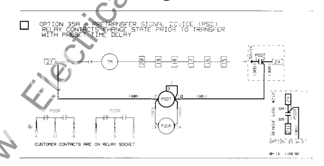
Thank you very much for your willingness to help!!! The short version is we have a Westinghouse ATS that does not have a pre-transfer signaling kit installed but we need one now since we are bringing the elevator up to code. The elevator inspector is requiring a connection between the elevator and transfer switch - a pre-transfer signal with a time delay. I know we need option 35A in the westinghouse transfer switch manual (see image) but I don't think it is available anymore. So I need an alternate option with parts that exist.
The longer version is that the hired contractor was told by someone they hired to land the wires on terminals 73 and 74 but when they went to test it they noticed a voltage of 120V on those terminals and figured that would not work. they called me in but I could not offer much help with something I am not an expert at. I made a few calls to some manufacturers and was told that terminals 21 and 24 are where i was going to be able to achieve the time delay and pre-transfer signal. Unfortunately, no-one knows what parts are needed or how we can achieve this. Hence why I am on this forum. I have attached some images of the transfer switch and we have found a few manuals so let me know if that would be helpful to have.

Thanks in advance for the help!

pretransfer_signal_device.PNG


https://hosting.photobucket.com/images/i/mevans004/20210225_100848.jpg
https://hosting.photobucket.com/images/i/mevans004/20210225_100824.jpg
https://hosting.photobucket.com/images/i/mevans004/20210225_100806.jpg
 
Ok, if you scroll back to post #2 I sent Jason a pic of a control circuit I designed for a job I did on the same exact West ATS that you show in you links.
The circuit for the panel is shown in the drawing you sent. The PSDR (Pre Signal Delay Relay) is the Idec cube relay #RH2B-UL, 120VAC. I labeled it PSR. The PSDT (Pre Signal Delay Timer) is the Omron Timer#H3CR, 120VAC, set for 20 sec. I labeled it PST. On the terminal strip you connect 21, 24 and 18 as shown in your dwg. Terminals A, B & C are the relay contacts 4, 12 & 8 that provide the pre signal to the elevator controls. The way it works is when the signal is sent to transfer the ATS, both the relay and timer energize (pre signal sent to elev.) Then after the timer times out, the PSDT contact closes and the motor TM energizes, transferring the ATS.
If you feel more comfortable, your other option is to buy an off the shelf module made by Kohler for their ATS's but can be used on any brand (see attached files.) I think they are still available. Google Kohler part# 297124.
What sounds simple to me (51 yrs doing controls) may be confusing to others. You may have to engage an experienced electrician or controls guy to help you. Hope this helps.

19014 Kohler LS module #297124.JPG13064 Presignal Panel (Idec_Omron).jpg 19014 Kohler elev presig dwg_294147.pdf
 

Attachments

  • 19014 Kohler elev presig dwg_294147.pdf
    66.6 KB · Views: 41
mbrooke, I suggest you scroll back to post #2 and click on the text file.
It may answer your question.


I can't thank you enough! I've been asking this questions every few months on this forum for 8 years now.

Set of wires run from the ATS to the elevator controls, but no one has ever really given me an in depth explanation, or simply "so the gen doesn't shut down with ATS in EM" which never made much sense since in for example Kohler ATSs the engine start will not drop until the ATS contacts are in normal.

Question though- why does rapid transfer cause the electronics to burn up? Why not a delayed transition ATS? How to elevator manufacturers deal with POCO blinks?

I can understand interlocking the cars to run one at a time on gen power- however the rest seems like it could be simplified.
 
Status
Not open for further replies.
Top