Enphase IQ Combiner PCS and PV backfeed breaker ampacity question

Status
Not open for further replies.

photonboy

Member
Location
Berkeley, CA, USA
Occupation
Ex roof monkey, current desk jockey
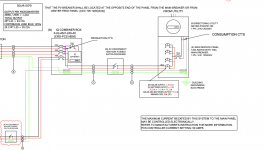
I'm looking at an Enphase system where the installer says that the output current to the MSP is limited to 50A by the Enphase PCS, which is also the max allowed on this panel. But they installed an 80A backfeed breaker since adding up the output currents of all of the microinverters and the battery and multiplying by 1.25 would require an 80A breaker.

They are claiming that the 80A breaker in a panel that will only allow 50A is just fine because they set the PCS at 50A.

I'm skeptical for two reasons, we have no clear way to determine if this setting is accurate and if it is limited to 50A why not install a 50A backfeed breaker?

Thoughs?
 

Attachments

  • Screenshot 2023-11-10 at 1.55.25 PM.png
    Screenshot 2023-11-10 at 1.55.25 PM.png
    475.8 KB · Views: 53
First of all the PCS current setting needs to be 40A so that 125% of the current does not exceed 50A.

As far as what allows it, 705.13 allows it, plain and simple.

As far as determining the setting is accurate, ask them to show you the documentation and the setting in the Installer Toolkit app. A tech should be able to do that with their phone on site.
 
Since the panel bus is rated 125-amp, is the setting at 50-amp permitted?

Do we call that Empower Smart Switch a PCS or a MID? Since I'm under the 2023 Code all my thoughts are 2023 related.
 
Do we call that Empower Smart Switch a PCS or a MID? Since I'm under the 2023 Code all my thoughts are 2023 related.

The Enpower Smart Switch, now known as a System Controller, contains the MID. It does not implement PCS. Also the OPs post and attachment doesn't mention or show one.
 
The service bus is rated at 125A. 120% of 125A is 150A. The main breaker is 100A. This allows for a max PV system OCPD of 50A. If a PCS is used, it should limit the system to 80% of the max PV system OCPD, which is 40A continuous current.

The OP's question is a good one, why use a breaker, disco, and presumably conductors sized for the full output of the system when it is required to be throttled back. It would be pretty easy to open the throttle after the inspector leaves.
 
Looking again at the OPs line diagram, it appears that there is both PV and batteries in the system (without backup, all grid tie only). So it makes sense that they should be able to use PCS to limit the output since there's no need for PV and battery to fully output at the same time.

However one thing I noticed is the battery output is listed as 20A on a 40A breaker, which seems wrong both because those things don't agree with each other and also because 20A doesn't correspond to any supported combo of Enphase batteries I know of.
 
The service bus is rated at 125A. 120% of 125A is 150A. The main breaker is 100A. This allows for a max PV system OCPD of 50A. If a PCS is used, it should limit the system to 80% of the max PV system OCPD, which is 40A continuous current.

The OP's question is a good one, why use a breaker, disco, and presumably conductors sized for the full output of the system when it is required to be throttled back. It would be pretty easy to open the throttle after the inspector leaves.

I think we’re all forgetting the intent of a PCS.

The reason you’d want to size at 80A is because if the consumption CT’s detect usage, the system will discharge the PV and batteries to as much as 80A (theoretical, in practicality less than that) to offset that max electricity going through the meter. It’ll never allow net output higher than the PCS setting; however, if the consumption at the site gets high enough, in theory this system will output up to 80a so long as no more than the max PCS setting is going through the meter.
 
The service bus is rated at 125A. 120% of 125A is 150A. The main breaker is 100A. This allows for a max PV system OCPD of 50A. If a PCS is used, it should limit the system to 80% of the max PV system OCPD, which is 40A continuous current.

The OP's question is a good one, why use a breaker, disco, and presumably conductors sized for the full output of the system when it is required to be throttled back. It would be pretty easy to open the throttle after the inspector leaves.
those settings per my knowledge is only accesible to manufacturer once the settings is changed, installers cannot change it as they want, i might be wrong but thats what i heard.
 
those settings per my knowledge is only accesible to manufacturer once the settings is changed, installers cannot change it as they want, i might be wrong but thats what i heard.

It has to be a qualified person, aka installer with training. It can be changed in the field.
 
I think we’re all forgetting the intent of a PCS.

The reason you’d want to size at 80A is because if the consumption CT’s detect usage, the system will discharge the PV and batteries to as much as 80A (theoretical, in practicality less than that) to offset that max electricity going through the meter. It’ll never allow net output higher than the PCS setting; however, if the consumption at the site gets high enough, in theory this system will output up to 80a so long as no more than the max PCS setting is going through the meter.
yes thats the motto, over all the grid current plus inverter current should not exceed 150A at once, in the event grid crosses 100A , pv should be curtailed at 50A.if grid current is 125A, pv should be curtailed at 25A. if the grid current is only 70A, the inverter should be able to supply 80A. but the practical execution of PCS I Have personally not seen myself at field yet but theoretically 80A breaker is righlty sized isnt it?
 
In this case the PV can output it's full output pretty much whenever, because it is less than 40A. The battery may be charging, or outputting. If the PV is not outputting, it appears the battery can output its full amount, if that's also less than 40A. However if both PV and battery are outputting then the total cannot exceed 40A.

Frankly I'm not sure that Enphase is supporting this mode yet, but there are several different features that have recently been rolled out or are coming soon. It is totally legit for an AHJ to ask after the details.

That’s a good question, the OP’s SLD is akin to their NEM3 solution, and I would imagine that with PCS enabled on MPUA mode, that it will discharge only the ESS if consumption is present, and PV only if not — depending on their grid profile and settings.
 
It doesn't depend on the grid profile. It does depend on settings. It will do different things on Self-Consumption or Savings mode. But regardless, given the line diagram shown, PCS needs to limit the output in a way that supersedes whatever would be done if consumption was greater than 40A.
 
It doesn't depend on the grid profile. It does depend on settings. It will do different things on Self-Consumption or Savings mode. But regardless, given the line diagram shown, PCS needs to limit the output in a way that supersedes whatever would be done if consumption was greater than 40A.

Take a look at the PEL section of the PCS technical guide. It does talk about how grid profiles play a role.
 
However if both PV and battery are outputting then the total cannot exceed 40A.
Not sure what this particular PCS is capable of, but you don't think that 705.13 et al would permit a PCS to monitor both the grid contribution to the 125A bus (via the CTs labeled "Consumption" in the OP diagram) and the inverter contribution to the 125A bus (from both PV and ESS), and impose only the joint limit that the sum is no more than 120% * 125A / 125% = 120A? Rather than rigidly limiting the total inverter output to 40A, regardless of the grid draw?

Cheers, Wayne
Honestly hadn't thought about it that way. I agree 705.13 would allow this.
 
Honestly hadn't thought about it that way. I agree 705.13 would allow this.
So that fits with the ideas in post #9, that the 80A OCPD and conductors, rather than 50A OCPD and conductors, are useful. Namely for the case that the loads are above 50A and the inverters can generate more than 50A and the ESS control strategy says it should discharge (peak rate period).

I did not look at the details of the inverter sizes in the OP, or of what the Enphase products can do, to check if this can happen in practice, but I would be interested in the answer.

Cheers, Wayne
 
I did not look at the details of the inverter sizes in the OP, or of what the Enphase products can do, to check if this can happen in practice, but I would be interested in the answer.

According to some info I have from a webinar, this functionally was supposed to become available for a grid-tied system within the last month. But I've not seen it in action so can't personally vouch they hit their timeline target.
 
Status
Not open for further replies.
Top