(EU Carpet cleaning machine) step up transformer help

Status
Not open for further replies.

JMWElectric

Member
Location
Martinez CA
I am currently in the process of trouble shooting a European carpet ringing centrifuge machine. I am the third or fourth electrician to tackle this thing and I guess nobody can get it to run or even turn on.

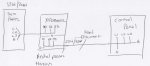
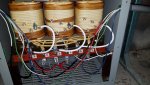
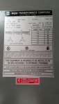
Currently there is a 3 phase 120v/208v sub panel feeding a 15 KVA step up transformer that is supplying this machine with 230v/420v I have attached a crudely made diagram of the layout. I would like to believe that the wrong transformer was used or even the taps need to be moved. When the control panel for the machine is disconnectd the voltage from the transformer reads L1 230v L2 230v L3 230v, but when the control panel is simply switched on the voltages change to L1 420v L2 420v L3 29v. Now I know that testing to ground may not even be correct through this transformer so the transformer company engineer has said but that is what the reading is anyway. Other then a few lights on the control panel nothing comes on when switched on.

I am willing to answer any questions to figure this out, I don't want to throw in the towel on this one.

Thank You
 

Attachments

  • Untitled.jpg
    Untitled.jpg
    15.8 KB · Views: 1
  • 20170621_110438.jpg
    20170621_110438.jpg
    154.5 KB · Views: 1
  • 20170621_104528.jpg
    20170621_104528.jpg
    146.6 KB · Views: 1
Chances are that the control panel has line to neutral loads while you are feeding it from an ungrounded delta. The motor would be fine with the delta, but not the control panel, so the controls do not work.
When you close the disconnect it is clearly putting some small load between L3 and ground, which is unbalancing the phantom voltages you are reading while the disconnect is open.

Sent from my XT1585 using Tapatalk
 
Here's a link that may be helpful:

https://www.mgmtransformer.com/pdf/mgm_bulletin_10.pdf

GoldDigger, isnt that xfmr schematic showing a corner-grounded delta, with the dotted line coming from X1/H1?

afaik, the neutral cannot come from the panel (primary) of a wye system and pass thru a delta xfmr to create a wye secondary; the neutral has to be derived by the transformer.

JMWElectric, do you have any pics or specs on the machine itself? Brand? Wiring schematics?
 
Last edited:
JMWElectric, do you have any pics or specs on the machine itself? Brand? Wiring schematics?


Yes the machine being hooked up is a CENTRI 420 made by Hanta systems in Greece the manufacturer recommended voltage states 3 phase 400v 50hz but the manufacturer stated in email that the control panel was set to run on either 50/60 hz and 3 phase 400v or single phase 230v which is what we are providing it. I have attached some more photos.


https://www.dropbox.com/s/iejrcmv8x5zxob0/Manual CENTRIFUGE_Cardoso.pdf?dl=0 Manual
 

Attachments

  • stegnwtiras_is7_no_fouskes_timer_SlowRamp_V6.pdf
    97.7 KB · Views: 0
Last edited:
Here's a link that may be helpful:

https://www.mgmtransformer.com/pdf/mgm_bulletin_10.pdf

GoldDigger, isnt that xfmr schematic showing a corner-grounded delta, with the dotted line coming from X1/H1?

afaik, the neutral cannot come from the panel (primary) of a wye system and pass thru a delta xfmr to create a wye secondary; the neutral has to be derived by the transformer.

JMWElectric, do you have any pics or specs on the machine itself? Brand? Wiring schematics?
Where would i acquire the neutral from the step up transformer? There is no XO

Sent from my SAMSUNG-SM-G891A using Tapatalk
 
Where would i acquire the neutral from the step up transformer? There is no XO

Sent from my SAMSUNG-SM-G891A using Tapatalk


Your voltage measurements as listed are not consistent with the grounded H1 terminal shown in your sketch.

As for how to get a usable neutral in your situation, you simply cannot do it using the transformer which the original electrical worker choose.
You need a wye secondary (wye on the motor side) OR you may be able to add a separate three phase transformer in zig-zag configuration to derive a neutral (not necessarily compliant!)
What size transformer would suffice to create this neutral? I have never done this before can you briefly walk me through this? Thank you in advance.

Sent from my SAMSUNG-SM-G891A using Tapatalk
 
Where would i acquire the neutral from the step up transformer? There is no XO

Sent from my SAMSUNG-SM-G891A using Tapatalk

You cant get a neutral from the secondary of the xfmr you have.

The one-line diagram you linked:

stegnwtiras_is7_no_fouskes_timer_SlowRamp_V6.pdf

shows that a neutral is needed, and so you need a delta-wye transformer. You could get a second transformer that derives a neutral (400V - 400/231Y), or something like this:

http://www.ebay.com/itm/TESTED-DONG...08V-to-380V-400V-220V-1-3-PHASE-/182627573307

that converts 208V input to a 400/230Y secondary, tho you need a 15kva one, assuming the xfmr you have is sized correctly.

This one:

https://www.temcoindustrial.com/temco-large-euro-standard-european-voltage-transformer-tt1031.html

converts 240V to 380/400/415V wye

You may want to check with that mfg to see if they have a 208V counterpart.

or this one:

https://www.platt.com/platt-electri...20-240/Acme/TP79087S/product.aspx?zpid=246330

in a 15kva model.
 
A CE marked machine shouldn’t be using 230V Ph+N for the control circuits. Normal practice is to have a 400/110V transformer built in to the control panel.

Could you post a photograph of the panel interior?
 
Last edited:
A CE marked machine shouldn’t be using 245V Ph+N for the control circuits. Normal practice is to have a 433/110V transformer built in to the control panel.

Could you post a photograph of the panel interior?

The second link in post #4 has the wiring diagram, tho a pic of the actual panel would be best. From what I can gather, there are 4 inputs: L1, L2, L3, and N. There's also a line labeled "PE", which I gather is "protective earth" (ground) - is that correct?
 
Looking at the attached schematic, the NEUTRAL is required to support the control system & a couple of blower motors. The schematic doesn't detail the HP of these but does show both protected by a 4A MCB so they can't be huge.

One possible way forward would be to install a smaller transformer (say, 1kVA, 400V primary to 230V secondary) to support these loads. Obviously this would mean modifying the machine wiring (usual cleavats etc) but is a possible way forward at much less expense than replacing the main 208/400 transformer.

Also, a note of caution here... these blower motors are expecting 50Hz. You will be supplying then with 60Hz - they are gonna want to spin faster. If they spin faster the fan will demand more mechanical power to move more air ... will the motor become mechanically overloaded??
 
I’d not seen the drawings.

Other than changing the ∆∆ to a ∆Y the only way is a separate 400/230V transformer as Adrian suggested.

To be honest I’d be wary of the second transformer, manufacturers are a slippy bunch when it comes to warranties.
 
Looking at the attached schematic, the NEUTRAL is required to support the control system & a couple of blower motors. The schematic doesn't detail the HP of these but does show both protected by a 4A MCB so they can't be huge.

One possible way forward would be to install a smaller transformer (say, 1kVA, 400V primary to 230V secondary) to support these loads. Obviously this would mean modifying the machine wiring (usual cleavats etc) but is a possible way forward at much less expense than replacing the main 208/400 transformer.

Also, a note of caution here... these blower motors are expecting 50Hz. You will be supplying then with 60Hz - they are gonna want to spin faster. If they spin faster the fan will demand more mechanical power to move more air ... will the motor become mechanically overloaded??

Guys,

There is no inexpensive workaround for this and if there is, it will probably not be code compliant. However, there is an easy solution.

You are trying to power a wye configured piece of equipment from a delta configured source. You are missing a neutral, and the only way to get one is to have it created by the transformer. You cannot pull a neutral from anywhere else, it wont work. The only reasonable solution is to replace the existing XFMR with a new 15KVA, 208V - 400Y/230V (Delta to Wye), 3-phase step-up XFMR.
 
I think you need a new xfmr.

I am not sure this is what is meant but it appears from the sketch that the N line going to the unit is from the line side of the existing xfmr and not the load side. That can't work.
 
You cant get a neutral from the secondary of the xfmr you have.

The one-line diagram you linked:

stegnwtiras_is7_no_fouskes_timer_SlowRamp_V6.pdf

shows that a neutral is needed, and so you need a delta-wye transformer. You could get a second transformer that derives a neutral (400V - 400/231Y), or something like this:

http://www.ebay.com/itm/TESTED-DONG...08V-to-380V-400V-220V-1-3-PHASE-/182627573307

that converts 208V input to a 400/230Y secondary, tho you need a 15kva one, assuming the xfmr you have is sized correctly.

This one:

https://www.temcoindustrial.com/temco-large-euro-standard-european-voltage-transformer-tt1031.html

converts 240V to 380/400/415V wye

You may want to check with that mfg to see if they have a 208V counterpart.

or this one:

https://www.platt.com/platt-electri...20-240/Acme/TP79087S/product.aspx?zpid=246330

in a 15kva model.
Never set up a zig zag transformer any way you could walk me through it a bit?

Sent from my SAMSUNG-SM-G891A using Tapatalk
 
Guys,

There is no inexpensive workaround for this and if there is, it will probably not be code compliant. However, there is an easy solution.

You are trying to power a wye configured piece of equipment from a delta configured source. You are missing a neutral, and the only way to get one is to have it created by the transformer. You cannot pull a neutral from anywhere else, it wont work. The only reasonable solution is to replace the existing XFMR with a new 15KVA, 208V - 400Y/230V (Delta to Wye), 3-phase step-up XFMR.

I agree that a whole new TX, ideally Delta/wye is the best way to go.

However, I'm not suggesting pulling a neutral from "anywhere else"... I'm suggesting adding another, smaller transformer, supplied from the secondary of the 15kVA (ie at 400V). The secondary of this smaller transformer would be 230V. The control/blower circuit would be completely disconnected from the existing feed (hot & neutral) and powered solely from this smaller TX.

I accept the point about warranty etc etc, only the OP can decide if this matters to the Client, but I can't see what code requirement tis would violate?
 
Status
Not open for further replies.
Top