Experiments with AFCIs and GFCIs

Status
Not open for further replies.

ELA

Senior Member
Occupation
Electrical Test Engineer
This tread was inspired by a previous thread where GFCI failure modes were discussed and another where an appliance caught fire and it was wondered why the standard upstream breaker did not trip.

In one thread ?Tool_5150? mentioned he found a Leviton GFCI with a coil blown apart. ?Gar? theorized that it might have been a shorted bridge diode or SCR.
In order to show the effects of a failed SCR on the Leviton unit I wanted to test this failure mode. Having previously been inspired by Gar to disassemble a unit.

In the other thread it was questioned how an appliance could catch fire without the breaker upstream having tripped. In that thread it was mentioned ?that was what AFCIs were for?. And a question, would a AFCI have prevented this?

I have been interested in working with AFCIs since I am not normally exposed to them.

I decided to combine the two devices into one experiment. I wanted to test the effects of a shorted SCR in the GFCI. Knowing that as the coil heated that it could possibly provide a lower impedance at some point in its failure I wanted some additional protection upstream. For this I used an AFCI.

Below is diagram of the test setup.
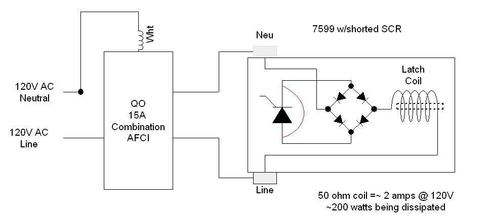
GFCI-AFCItest.jpg


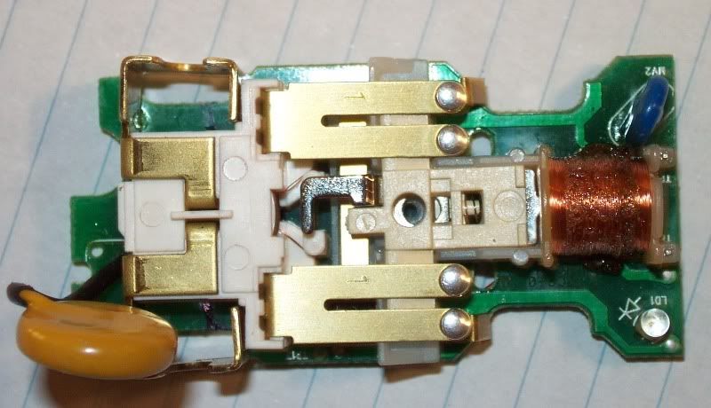
Here are two pictures of the GFCI coil one prior to the test and one after.
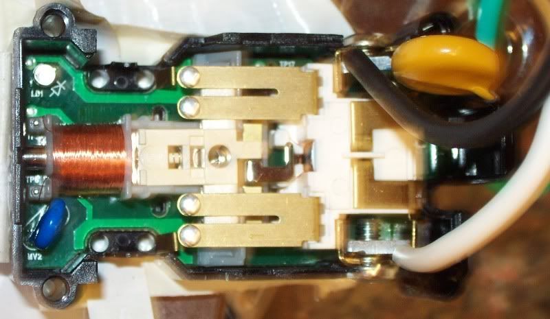
coilbeforeR.jpg


coilafter2R.jpg


It only took about 3 seconds after the application of 120V for smoke to start to appear and the coil burst into a small flame as the coating on the wire burnt. The flame only lasted a few seconds and died out.

From this test it is apparent that a shorted SCR can indeed cause severe damage to the coil and that it will happen within seconds.

I also found it interesting that a small flame appeared and the AFCI did not trip.
Please note that the coil was exposed (unlike in normal operation) and from what I saw it would be unlikely to actually start a house fire in a normal installation.

But still interesting. The series arc created as the coil burning open must never have exceeded 5 amps? From the looks of the coil it did not fail severely enough to cause any low impedance parallel arcing.

I took crude video and will post that shortly if I can.
 

ELA

Senior Member
Occupation
Electrical Test Engineer
Here is the video if it works:
http://s268.photobucket.com/albums/jj22/transorb/?action=view&current=CoilMishap1.flv

Not the best quality. If you look close you can see the coil energize after 3 seconds.

Afterwards the coil measured open circuit. Two of the diodes in the bridge measured as shorts at this point.

The circuit traces were all intact so the weak link was the small diameter coil wire (and the fact that it was dissipating a high wattage).
 

gar

Senior Member
Location
Ann Arbor, Michigan
Occupation
EE
080912-1105 EST

ELA:

Good experiment and a neat picture of the fire ball.

Interesting that two diodes failed because of the SCR being shorted. I might have expected a somewhat better I^2*T capability for the diodes.

Thanks for the experiment.

.
 

wptski

Senior Member
Location
Warren, MI
ELA:

I also found it interesting that a small flame appeared and the AFCI did not trip

The above is a typo, correct? This is a GFCI not a AFCI.
 

ELA

Senior Member
Occupation
Electrical Test Engineer
As I mentioned I was not directly familiar with AFCIs from practice.

I bought a small 2 circuit panel to house the AFCI for my experiment. I also reasoned that I could later install the AFCI in my home load center on a circuit.

As often is the case things don't go according to my plans:roll:

These AFCI's are humongous!

Due to my lack of experience it did not occur to me in adavance that this AFCI breaker would not fit in the small two circuit cabinet. I ended up severely modifying the box (will only be used in this fashion once) for this experiment.

That made me worried about the AFCI fitting in my load center.

The AFCI measured 4.75" in length vs 3.875" for a GFCI breaker that was already in my load center.

Sure enough my load center is only a 12" wide box. 4.875 + 4.875 = 9.75" that only leaves about 1.1" on each side for connections and other circuits wiring (based on two AFCIs side to side).

So I will not be installing this AFCI in my home cabinet until I am willing and ready to take on a complete load center change. Just too many other wires in the path! Not a pretty sight this load center.

I am curious...
I would think this issue would come up regulary for electricains who do service upgrades and circuit additions and have either a desire or requirement to install AFCIs?

p.s. I tried my large vacuum and the AFCI held ;)
 

ELA

Senior Member
Occupation
Electrical Test Engineer
gar said:
080912-1105 EST

ELA:

Good experiment and a neat picture of the fire ball.

Interesting that two diodes failed because of the SCR being shorted. I might have expected a somewhat better I^2*T capability for the diodes.

Thanks for the experiment.

.
Thanks Gar,
I just could not resist seeing that coil burn ( I missed Burning Man this year) :grin:


The diodes being shorted did not surprise me. I wish we could read the part numbers on these small parts. I estimate the diode to be a DO-214AC package and probably rated at 1 amp continuous.

Under normal conditions these diodes only have to carry 2amp coil current for 1/2 cycle or so. They are just fine for this very light duty.

Here we stressed them with 2A * 1.1V or 2.2 Watts for seconds.
From a couple of possible example diodes in these package sizes they have a possible thermal resistance of 75C/watt or more.
At 2 amps that junction was getting too hot fast.
 

gar

Senior Member
Location
Ann Arbor, Michigan
Occupation
EE
080913-1830 EST

ELA:

The Diodes Inc, datasheet for a S1GB shows a thermal resistance of 30 deg C/W and therefore it should be good for this type of load at room temperature. Voltage may be more likely to short closed, but with overheating for a limited time this might also cause a permanent short. When the coil opens this may produce a large surge voltage, but we have that MOV directly across the bridge AC input. It is not clear what is happening to cause the diode failure.

A reference I found indicated dominate failure is short on voltage, open on current. Initially current may short and then biurns open.

.
 

ELA

Senior Member
Occupation
Electrical Test Engineer
Gar,

Your eyes are better than mine. Neat that you could read the part number.
The 30C/Watt rating is junction to terminal. The higher number I stated was junction to ambient.

I have purposedly shorted bridges before and had the same result of a shorted diode or two.
It could be a fluke? Maybe a second experiment would not show shorts?
I do not care to over think it.
That is the cool thing about actual experiments vs. theory. It is what it is.
 

gar

Senior Member
Location
Ann Arbor, Michigan
Occupation
EE
080913-1924 EST

ELA:

I do not know what diode is in the Leviton, I just took a diode I have of the same package, and current rating you indicated, then a looked at its datasheet. The Diodes, Inc. datasheet has a note on heatsinking to a pc board.

Yes experiment is always the final test. That is why anyone that can report on actual field failures, apparent failure points, and causes can be very useful to others in making decisions.

.
 

mxslick

Senior Member
Location
SE Idaho
Great test..

Great test..

ELA:

Thanks for the test and video..it was interesting to see the actual results of a GFCI failure.

Edited to add: If you look closely, right before the end of the vido you can see a smal arc at the lower right of the coil..maybe one of the diodes failing?

I wonder if a similar failure mode was going on when others have mentioned that keying a two-way radio would kill some brands of GFCIs'.
 
Last edited:

LarryFine

Master Electrician Electric Contractor Richmond VA
Location
Henrico County, VA
Occupation
Electrical Contractor
This coil burnout seems very similar to a shunt-trip breaker not having its trip power immediately removed.

The GFCI tripping is supposed to remove the power from the coil, right?
 

gar

Senior Member
Location
Ann Arbor, Michigan
Occupation
EE
080914-0846 EST

Larry:

The design of the Leviton that we have been talking about has the coil in series with a bridge rectifier, the current transformer, and with an SCR across the DC output side of the bridge. This is hung directly across the line input terminals. The breaker contacts never open this supply to the coil.

Normally the load on the DC side of the bridge is not very large. When a trigger condition occurs the SCR is turned on and this shorts the DC supply to the trigger circuit and thus the signal to the SCR gate. The ON SCR provides about a 2 A pulse to the coil. This may last longer than 1/2 cycle depending upon the energy stored in the trigger circuit. The SCR will turn off each 1/2 cycle, but if there is still enough energy from the trigger circuit to supply adequate gate current, then the SCR will be turned on again. I have not experimented with the circuit to see how many half cycles of current flows to the coil.

If for external reasons, like a large voltage spike, one of the diodes is shorted or the SCR, then there will be continued current flow at about 2 A thru the coil and it will burn up.

.
 

ELA

Senior Member
Occupation
Electrical Test Engineer
Larry,

It appears that earlier versions of the GFCI did remove power from the coil after it tripped as can be seen in the LM1851 data sheet schematic (was presented in other posts). In some ways this seemed like a better design? I am not sure why they changed it but probably had to do with the new coil latch mechanism Gar has explained in other posts.


Gar,

I did measure a few true trip cycles on the GFCI before I opened it and most were 1/2 cycle at 3 amps peak. I was not looking for in-depth data at the time, I was just curious.
I had thought about going back and taking a closer look at the trigger circuit. I don't usually have a lot of spare time for experiments like this. I want to do a little more testing on my new AFCI.


Mxslick,

That small arc at the end was cool to see. It is just a piece of the coil insulation I believe. The diodes are on the other side of the pcb from what you are looking at.

This is a type of testing I have done before for UL certifications of equipment. You purposely short out high voltage components, one at a time and document the results. In a "real" test the unit would not be open like in the video. In the actual test you then put a piece of cheesecloth over the top to see if the cloth will catch fire or be affected in any way during testing.
In the test I did the fire only lasted a few seconds. If done inside of the normal enclosure I doubt you would see any effect external to the unit.


I have also done a bit of EMC (Electromagnetic Compliance testing) in the past. We used radio frequencies to upset electronics to test for their level of susceptability. In this testing it usually only causes a temporary upset of the equipment (like a nuisance trip).

Have you experienced radio interference that tripped a GFCI and it could then not be reset again? That would be interesting to investigate.
 

ELA

Senior Member
Occupation
Electrical Test Engineer
The other site seemed to reduce the video quality to even less than the initial poor quality of my little $14 web cam.

I wanted to try this. It seems better if you select high quality viewing mode?

watch
 

ELA

Senior Member
Occupation
Electrical Test Engineer
ELA said:
Larry,

It appears that earlier versions of the GFCI did remove power from the coil after it tripped as can be seen in the LM1851 data sheet schematic (was presented in other posts). In some ways this seemed like a better design? I am not sure why they changed it but probably had to do with the new coil latch mechanism Gar has explained in other posts.


Mxslick,

I have also done a bit of EMC (Electromagnetic Compliance testing) in the past. We used radio frequencies to upset electronics to test for their level of susceptability. In this testing it usually only causes a temporary upset of the equipment (like a nuisance trip).

Have you experienced radio interference that tripped a GFCI and it could then not be reset again? That would be interesting to investigate.


I was thinking some more on this and do think I like the original design better in terms of removing the coil power as well as power to the LM1851 when tripped. It may have made it more difficult for them to have met the new requirements for test at the time of reset but better in other ways.


In doing EMC testing I also performed EFT (Electrical Fast Transient) tests. This is like a burst of fast transients. Not as much energy as Surge testing but more repeative broadband noise is created. This type of testing could cause ICs to latch up and microcontrollers to reset. A power cycle would sometimes be required to recover from this.
So with current design it could be conceivable to latchup the IC and cause an upset. The device may not then be able to perform the reset function without cycling power. In the old design at least if it did nuisance trip it removed its own power.

I mention this as a possible help in troubleshooting GFCI problems. Before considering the GFCI defective it might be prudent to remove the line power and re-apply to see if it recovers? Like a re-boot :grin:
 

LarryFine

Master Electrician Electric Contractor Richmond VA
Location
Henrico County, VA
Occupation
Electrical Contractor
gar said:
The design of the Leviton that we have been talking about has the coil in series with a bridge rectifier, the current transformer, and with an SCR across the DC output side of the bridge. This is hung directly across the line input terminals.
It looks to me that the bridge is used to allow the use of an SCR instead of a triac.
 

gar

Senior Member
Location
Ann Arbor, Michigan
Occupation
EE
080914-1437 EST

Larry:

The bridge circuit is needed to provide DC for the electronic circuit. Then by putting the SCR across the DC output of the bridge and when the SCR is trigger it has the byproduct of forcing the DC supply to near zero and thus cutting off the drive to the SCR gate, and in turn deactivating the SCR.

ELA has indicated that his tests typically showed a 1/2 cycle pulse.

.
 
Status
Not open for further replies.
Top