Exploding lightbulbs

Status
Not open for further replies.

jjhoward

Senior Member
Location
Northern NJ
Occupation
Owner TJ Electric
Hi Brian,

I haven't heard from this customer again.

I guess it is possible that they have a problem with MWBC.

I'll check in with them. It wouldn't be the first time I find out that a customer has been living with some serious problem for weeks or more and just hasn't gotten around to calling anyone about it.
 

Energy-Miser

Senior Member
Location
Maryland
nakulak said:
here's a nice link that does a great job explaining rms
http://www.ultracad.com/articles/rms.pdf
Yes, clear and accurate explanation. It states too that meters that are not "True RMS" will not be accurate with non-sinusoidal waveforms. Even with True RMS meters, only the newer models are to be trusted with non-sine waves, or distroted sine waves (since these newer models are computationally based and can analyse practically any waveform). e/m
 

Energy-Miser

Senior Member
Location
Maryland
brian john said:
True RMS meters are required for multimeters and clamp-ons. I tried to locate a distorted voltage sine wave but only was able to locate this snapshot...Posted previously...
Brian,
This is apparently a snapshot of the currents for a 3-phase Y connected load (is that fair to assume?). If so what was the load, a motor? I am interested in knowing what kind of load generates the non-linearities shown in the snapshot. Thanks, e/m
 

76nemo

Senior Member
Location
Ogdensburg, NY
Distortion

Distortion

You can look at a branch with several computers, look at IT equipment, look at almost anything utilizing SMPS's, you can see it. YOU can see it with an averaging clamp compared to an RMS clamp.
Look, posts #47 and #50 were a test on my part. I wanted to see just how bad I got hammered. Thought a couple here would grill me, and leave me for the buzzards. That's what I was betting.
I sometimes like being wrong.

Okay, you asked for it, now don't complain about it for being too long. The Ideal 61-165? What does it do for me? I didn't look to see what the post # was that started my interuption, but start there. How many times have loose wires been the root of the problem over a long period of time or with a heavy load?

Someone made a jab about not using a better brand than IDEAL. I use and buy only one particular brand of testers. I have always frowned on IDEAL testers, to me they always looked cheap, almost like a child's toy. Rugged never crossed my mind with that company and their testers. The only thing I carry that is not Fluke is #1.Phase Sequencer, #2.IR gun, #3. Mag-Probe. I was very skeptical on spending more money on my disease. After talking with a friend who bought one, and hunting for a good deal, I broke down and bought one.
So, reasons in a long nutshell?,.........Time, product features, ease and comfort. Did I fit speed in there?

LOOP IMPEDANCE!!!!!! IEEE states EGC to have less than .25 ohms to be safe. Lose a neutral? Here, plug this in. Wiring configuration, big deal right? It can determine N to PE, excuse me, grounded to grounding bonds 15-20' upstream. Instant Vdrop, 12, 15, 20A loads. Grounded to grounding V, peak, available short circuit current. Compare grounding to grounded V's on three ph and see imbalance or HD on a joint neutral. Ease of use, and design.

In the word of it's manual, they word it better than I can without this post being three times the size it is right know. All of those features plus more, all in a comfortable tester. Scroll down, down, down, until you find the feature you need. The only thing the tester askes of you is that you give it a minimum of 20 seconds from pull and plug to the next device to avoid overheating.

It's just a new type of testing for me I have never done before. Give me a circuit with a loose connection. You take the megger, that's if you can close that branch, and give me the SureTest. I'm betting I am out in the truck with your lunch ready before you get there. You are pulling boxes, disconnecting devices, removing the branch, blah, blah, blah. I'm plugging, graphing and going. You took the megger and tool pouch on your trial, I took the 61-165 and a Twix bar. When I find the fault, then I'll go grab the tool bag. Lighting circuit? Grab a 61-183 adapter, clip, clip, clip. Downstream to upstream all day long. With possible loose connections causing burden on anything, I'll take the 61-165, you take anything you want, but my lunch is getting cold:wink:
 
Last edited:

ELA

Senior Member
Occupation
Electrical Test Engineer
Be wary of the accuracy of measurements if the meter is not a "true RMS" meter and you are unsure of the distortion level. In addition check the specifications of the meter for the "crest factor" rating.

Good quality test equipment will list the crest factor rating in the specifications. The Fluke 87 being one.

Here is another link that explains this pretty well.
pg 182 has information on crest factor.

http://books.google.com/books?id=ho...4Nt7&sig=aZSgqNw2RqACK9pn-fuSjRl40f0#PPR20,M1
 

wptski

Senior Member
Location
Warren, MI
Is there a difference in "True RMS" and "RMS" or is "True RMS" just Fluke-speak?

I know that at least one Fluke product which is RMS but not marked at all or mentioned in its specs! That being the 1507 insulation tester.
 

ELA

Senior Member
Occupation
Electrical Test Engineer
wptski said:
Is there a difference in "True RMS" and "RMS" or is "True RMS" just Fluke-speak?

I know that at least one Fluke product which is RMS but not marked at all or mentioned in its specs! That being the 1507 insulation tester.

Looks like that meters primary intent is for resistance measurements?
It also happens to measure voltage. From the fact that they do not state the crest factor I would not trust it for RMS measurements.

I would also not trust the term "true RMS" alone as that may just be sales lingo.
This is why I have suggested that a person check the "crest factor" of the meter to be sure. If it is a good quality meter that is accurate for measuring distorted waveforms I suspect they will publish the crest factor.
 

76nemo

Senior Member
Location
Ogdensburg, NY
brian john said:
This was a TV studio

Not raining on the Ideal but I would not use a meger to check for an open circuit.


Ahhhhhh, TV studio,...bingo!
Brian, I guess I owe you an apology, and I'll always be the first to dish 'em out. When I first spoke of the SureTest, and finding the guys loose connections with it, you stated it was no replacement for a megger. I agree! Yeah, you can use a megger to find low resistance points, but nowhere near how fast you can with a loop impedance tester. Pick a conductor, press the arrow button, there's your results.

Sorry Brian. This is one of the very reasons I hate to brag about test equipment. I haven't heard back from anyone else who has one. Have you used one Pierre?
 

ELA

Senior Member
Occupation
Electrical Test Engineer
Your request for a test method tempted me to think about how you could develope a test based on the first link I provided. That link showed the crest factor value of a square wave or pulse train.

I was thinking you could calculate the RMS value. Then measure it with a meter and see if agrees with your calculated value.
Then I came across this:

http://www.enginova.com/true_rms_volts.htm

From that it appears things get even more complicated.

You could still use a triangle waveform that is symetrical about zero. Its crest factor was listed as 1.732 . You could calculate the RMS and then do a measurement test on a triangle wave. I think most decent true RMS meters will handle a crest factor up to 3.

Beyond that I think testing might involve using a more complex or distorted wave with a known or calculated RMS value (and symetrical about zero).
 

76nemo

Senior Member
Location
Ogdensburg, NY
Time

Time

Calculations, pencil and paper, laws/theory? I like that,.... to stay fresh. But I am speaking of TIME. BOOM, (as the young kids say), there it is. I'll say it again. You use ANY meter/tester you want with a possible loose connection. I'll take a loop impedance tester. We'll trade methods. I'll follow yours, you check out mine. Again, loop impedance is something I am new to. I eyeballed the Fluke 1653 for quite a long time. It isn't available in the US, and is way over my price league for something I did NOT know if I would benefit from or not. My buddy told me he got the SureTest and really liked it. I took his word, and watched for the best price. Hey, if I don't like it, I can always sell it and get my money back, right? You WON'T see me selling mine.
 

ELA

Senior Member
Occupation
Electrical Test Engineer
wptski said:
I'd like a link on "How to test if my DMM is RMS or not".


I had some spare time today. I had wanted to revisit this RMS, meter, crest factor measurement. I did some tests using a Laserjet printer, a scope and a few different meters we had around.

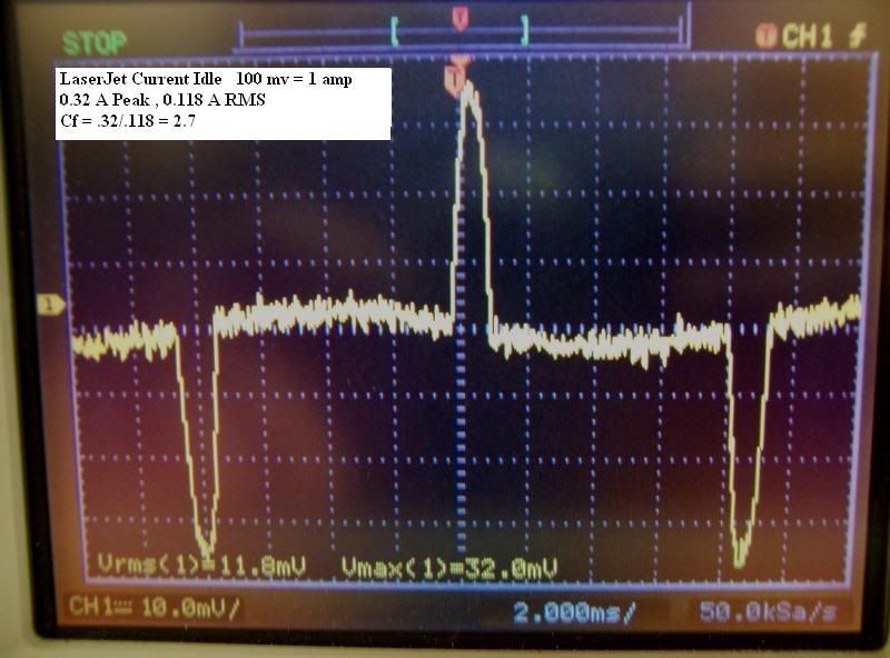
As it turns out this LaserJet was a perfect source for a highly distorted current waveform when running idle. Here is a scope image of that current waveform along with what the scope calculated for the RMS value.

Laserjet_Idle.jpg


I then measured this same current using meters with the following results:

Oscope = 0.118 amps RMS
Fluke 87 = 0.10 amps RMS
Fluke 79III = 0.10 amps RMS
Fluke 77III = 0.06 amps
Fluke 73II = 0.05 amps

I don't know if I trust the Oscope or the Fluke 87 more but they are close enough for me with this low level current.
Both the 87 and 79III claim to be True RMS and measure accurately.
The others neither claim to be true RMS nor do they measure accurately on this distorted waveform.
 

wptski

Senior Member
Location
Warren, MI
ELA:

RMS = .707 x Peak or .707 x .32 = .226. Where'd it get .118?

Specs for True RMS DMMs even on the top of the line run from 2-3% to 100% of range, so the low end is iffy! I've been playing with this myself also.
 

ELA

Senior Member
Occupation
Electrical Test Engineer
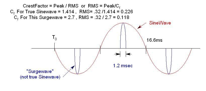
CrestFactor-1.jpg


Here is a comparison of a true sinewave as compared to the waveform of the LaserJet current. You can see that the LaserJet "surge current" only flows for a very small portion of the normal 60hz sinewave time. Can you see intuitively that there would be less electron flow when averaged over the 16.6 ms time for the surge wave and thus less RMS value.
 

wptski

Senior Member
Location
Warren, MI
ELA:

Of all the searching/reading that I've done concerning True RMS lately, I've never heard of the term surgewave and/or a different constant other than .707 or 1.414. Where did you ever find this info?

So, your saying that anything less 16.6ms/60Hz, you'd use a different formula? Is there a rule?

EDIT: What about a distorted voltage waveform and inrush currents?
 
Last edited:

ELA

Senior Member
Occupation
Electrical Test Engineer
Sorry Bill,
I think I made up the term "Surgewave" as a way of distinquishing it from the true sinewave. It was not meant to be the same as inrush current.


The 1.414 ratio only applies for true sinewaves. When the waveform is distorted or not a signwave the 1.414 no longer holds.

The "surgewave" has a period equal to a 60hz sinewave but you can see that the current pulse duration is much less than the 8.3 ms and so it can no longer be considered a true sinewave.

The RMS conversion factors from peak can all be derived from some more complex math. If you do a search on RMS conversion you can see those equations.

In the case of this experiment I had the advantage of using the Oscope which did the complex RMS math for me. The measurements with the True RMS meters then allowed me to confirm the Oscopes conversion.

One of the links I provided earlier in this thread gave examples of a few common waveforms and their associated crest factors. When the waveform is not a common waveform or a distorted waveform then more complex math is required to do the RMS conversion. Of course if you already know the crest factor and the peak value then you can use those to easily calculate the RMS value.

The digital Oscope is such a handy tool in this case to provide you with both the peak and the RMS value.

As far as inrush currents they are sometimes sinewaves and some times are not. They also usually only last for a few cycles so are best measured using an Oscope. For most of my work I have usually only been concerned with the peak values of inrush current and not so much with the RMS value.
 
Status
Not open for further replies.
Top