Alwayslearningelec
Senior Member
- Location
- NJ
- Occupation
- Estimator
Just curious how is the duct detector wired to a FSD? A FSD usually get 120v but what size FA wire is usually used?
Power to the FSD is routed through the on-board form "C" relay, which is typically rated to 10 amps or so at 120VAC. The connection depends on whether or not you are using the NO or NC side of the relay. The power to the damper is likely non-power limited, use Article 300 wiring methods suitable for the environment. This means likely no "fire alarm" wire (FPL, FPLR, or FPLP).
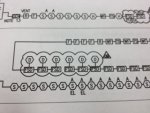
Just to let you know I am not taking this off it was an old drawing and I am trying to learn from it. But the ducts and fsd are on the same loops as the pulls stations etc. so aren't they connect with initiating circuit(fire alarm wiring)
Ah, I see what you're talking about. I don't know of any major fire alarm manufacturer who makes an addressable fire/smoke damper, and that seems to be the only thing that would make any sense in this case. As far as I know, FSD's aren't alarm devices and so have no business on an indicating device circuit (IDC, conventional) or signal line circuit (SLC, addressable). While we're at it, someday I'm going to brain an architect or three with a copy of NFPA 170 to try and convince them to use the standard device symbols instead of their in-house junk.
Taking the drawing at face value, I can't tell what's going on here. Especially since there is a break in the group of FSD's located inside the cloud. Without seeing the full sheet and the notes, I'm leaning towards "crappy riser diagram" :thumbsdown: as the answer to your question.
Sorry, just noticed it shows and was stated about the duct detector. Same situation applies as above, except the Duct detector IS the addressable relay, and you use the relay output on the duct detector to switch the PAM-SD.
This information only applies to addressable systems.
Sorry, just noticed it shows and was stated about the duct detector. Same situation applies as above, except the Duct detector IS the addressable relay, and you use the relay output on the duct detector to switch the PAM-SD.
This information only applies to addressable systems.
This is possibly what's happening, but you "assume facts not in evidence". Note that the FSD's are shown connected on the alarm loop, while the duct detectors are t-tapped off the individual FSD's. This makes no sense. And what about the break in the loop??