JoeStillman
Senior Member
- Location
- West Chester, PA
- Occupation
- Electrical PE
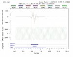
It's hard to see, but it looks like a C phase to ground fault to me.
Thanks, that's what we thought. But I'm puzzled why it settles down after only 2 cycles, and it looks like I have balanced (slightly increased) currents until the breaker opens at 9 cycles.
Thanks, that's what we thought. But I'm puzzled why it settles down after only 2 cycles, and it looks like I have balanced (slightly increased) currents until the breaker opens at 9 cycles.
That’s what I was wondering when I looked at it. I expected it to be longer.
thats why I suggested SEL syncrowave. There you can see the phasers rotate through the fault.
two cycles almost seems like something falling through.
without knowing 51 pickups and curves I’m only guessing though.
im assuming it opened on 51N.
is fault locate on for this relay?
I'm pretty sure that printout is from Synchrowave. This distribution is all underground downstream of this gear - about 50 transformers on 8 loops serving a college campus. The breaker that tripped is one of the mains in a main-tie-main arrangement. There is a 2MW combined-heat-and-power generator connected to this side of the bus via a wye-connected transformer. This breaker and all of the loops have (coordinated) ground-fault-instantaneous and that is what tripped in the main. None of the branches nor the generator tripped on ground fault. That would imply that the fault is on the substation bus somewhere, but there is no evidence of an arcing fault inside this brand-new switchgear.
The utility relays upstream have no instantaneous GF - just very-inverse. I've proposed eliminating the instantaneous on this main as well. The POCO has to approve a change in relay settings and they've promised to get back to me - in EIGHT WEEKS!
I think it's possible that this was a ground-fault on the line upstream and the generator fed the GF current. POCO ignored it because no 50G, only 51G. I wish I could tell from the Synchrowave what direction the current was going.
This breaker and all of the loops have (coordinated) ground-fault-instantaneous and that is what tripped in the main. None of the branches nor the generator tripped on ground fault.
that would explain the short duration.
is the 50 in the SER?
maybe look at the 1/4 cycle event data if it’s available. It will also give you degrees and you will be able to see the reverse flow
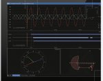
It would be great to see the phasor rotate through the fault. It looks like it, but during a fault the currents go all over the place. Upper right, little clock symbol, move the time back and forward a little to see the phasor movement. You can specify the time also.
I only say this because when you take the evidence to the POCO you need to have your stuff 100% to prove it.
get a phasor screen, then drag the cursor through the event to see the phasor rotate, you should be able to see it change direction from CCW to CW. Upper right, make sure rotation setting is set correctly though.
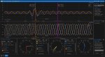
I was able to make an animated GIF showing the orange cursor sweeping across the fault. You can see the current phasor swing around 180° and back. Tried to upload it but the forum software doesn't like my file.
https://filebin.net/t5aay0tzd7t09fr2...GIF?t=015zj9u9
Nice. Definitely shows the complete 180 reversal in the phase C current.
Do you know if there's a separate current transformer for the neutral, or is the neutral current derived from the sum of the line currents (using a physical connection of CTs or software)? The reason I mention this is that in your original post the neutral current (and also IG) is in phase with all of the line currents. Even if there's reverse current flow from another source I would expect Kirchoff's law that all currents sum to zero would still apply. If there's a separate CT for neutral, is it possible the polarity is reversed somehow and this could cause an erroneous ground fault detection because the measured neutral current would not (at least partially) cancel out the measured line currents. I'm not very conversant in MV hardware so if I'm full of it let me know :blink: