You are using an out of date browser. It may not display this or other websites correctly.
You should upgrade or use an alternative browser.
You should upgrade or use an alternative browser.
feeder schedule
- Thread starter rose1981
- Start date
- Status
- Not open for further replies.
jojo
Member
- Location
- Philippines
- Occupation
- Electrical Engineer
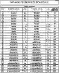
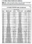
Hello rose1981, I think you still have to check it for verification, see attached. Per table the sizes are "based on the rating of the overcurrent protective device." To compensate for voltage drop (more than 100ft), we need to upsize the feeders.
Attachments
jojo
Member
- Location
- Philippines
- Occupation
- Electrical Engineer
Hello rose1981, I think you still have to check it for verification, see attached. Per table the sizes are "based on the rating of the overcurrent protective device." To compensate for voltage drop (more than 100ft), we need to upsize the feeders.
My mistake, let me rephrase. My words are confusing
") What I mean is we size the cable based on the attached feeder schedule (i.e. as a minimum, conductor shall match with the overcurrent protection device). But if the load is more than 100ft, we upsize the feeder to compensate for voltage drop.
What I mean is we size the cable based on the attached feeder schedule (i.e. as a minimum, conductor shall match with the overcurrent protection device). But if the load is more than 100ft, we upsize the feeder to compensate for voltage drop.- Location
- New Jersey
- Occupation
- Journeyman Electrician (retired)
Should I size the cables based on the over current protective device rating as per feeder schedule attached? or do a voltage drop calculation to size the conductors?
Generally the OCPD size wouldn't change even if the conductor were sized larger for VD compensation.
For example, say you need a 200 amp feeder for a 200 amp panelboard which would typically be #3/0, if you up-sized to 600 kcmil for an extra long distance then the feeder would still be a 200 amp feeder making the OCPD would then be 200 amps. In this example the panelboard is only rated for 200 amps so even though you have larger conductors you cannot exceed the 200 rating of the panelboard.
kwired
Electron manager
- Location
- NE Nebraska
- Occupation
- EC
If you increase conductor size because of voltage drop reasons, but leave overcurrent protection the same, then you must increase the equipment grounding conductor size proportionally to what you increased the ungrounded conductor sizes. This is pretty clearly stated in 250.122(B).
- Location
- Lockport, IL
- Occupation
- Semi-Retired Electrical Engineer
The sequence of design steps should go as follows:
The feeder schedule can be a handy tool for step 2. But it can give you an incorrect EGC size if you use it for upsizing for VD. You may have to calculate the upsized EGC manually.
- Calculate the load.
- Select a conductor size that has sufficient ampacity for that load.
- Select an overcurrent protection device that can protect that conductor size.
- Check for voltage drop issues, and decide whether to upsize the conductors and the EGC.
The feeder schedule can be a handy tool for step 2. But it can give you an incorrect EGC size if you use it for upsizing for VD. You may have to calculate the upsized EGC manually.
petersonra
Senior Member
- Location
- Northern illinois
- Occupation
- Semi-retired engineer
If someone gives you a drawing that already has the OCPD and wire sizes on it, why would you think it is your job to change them, unless you are being paid to proof them, other than for obvious mistakes like typos, or undersized wires.
Carultch
Senior Member
- Location
- Massachusetts
If someone gives you a drawing that already has the OCPD and wire sizes on it, why would you think it is your job to change them, unless you are being paid to proof them, other than for obvious mistakes like typos, or undersized wires.
The burden should be on the engineer to provide length estimates that are realistic for the project, for the major feeders, and provide the comprehensive feeder specification accounting for both voltage drop and local factors.
The engineer cannot always predict the path length. So if you take a path that is much more serpentine, far exceeding the length that the engineer predicted, then either know how to upsize it yourself, or ask for clarification.
Carultch
Senior Member
- Location
- Massachusetts
Generally the OCPD size wouldn't change even if the conductor were sized larger for VD compensation.
For example, say you need a 200 amp feeder for a 200 amp panelboard which would typically be #3/0, if you up-sized to 600 kcmil for an extra long distance then the feeder would still be a 200 amp feeder making the OCPD would then be 200 amps. In this example the panelboard is only rated for 200 amps so even though you have larger conductors you cannot exceed the 200 rating of the panelboard.
In that example, you'd probably have to make a terminal adaptation as well.
Because many engineers make drawings or project spec's that have a disclaimer in them putting Code compliance on the contractor. While voltage drop isn't a Code compliance issue, making certain voltage drop will not degrade equipment operation and such is something a conscientious contractor/electrician will do if there are no indications of a comprehensive analysis has been done (IMO).If someone gives you a drawing that already has the OCPD and wire sizes on it, why would you think it is your job to change them, unless you are being paid to proof them, other than for obvious mistakes like typos, or undersized wires.
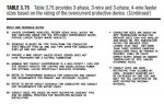
What I'd like to know is how you know Table 3.75 and the notes thereto are the same on rose1981's project when you are a half a world away???Hello rose1981, I think you still have to check it for verification, see attached. Per table the sizes are "based on the rating of the overcurrent protective device." To compensate for voltage drop (more than 100ft), we need to upsize the feeders.
jojo
Member
- Location
- Philippines
- Occupation
- Electrical Engineer
What I'd like to know is how you know Table 3.75 and the notes thereto are the same on rose1981's project when you are a half a world away???
Hello Smart $, even if Im a half world away were still in the same page in one way or another. Im working in a US based company here, hehehe ?
- Status
- Not open for further replies.