Adamjamma
Senior Member
- Location
- Jamaica and london
was watching the following video: https://www.youtube.com/watch?v=ItJ0YNOZ4wA
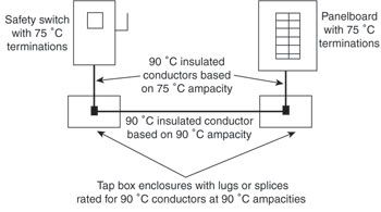
OK, one of the parts was about reducing the size by splicing using 90 degree connectors outside the breaker panel...
so, if you were using this, you size the feeder at 125 % load for only the distance from the cutoff device, to the splice position, and the same at the other end , from that splice position to the breaker feedpoint, or main breaker, if not using lugs, because these positions are only rated for 75 degrees.
the section in between you rate for just 100 percent, but due to the length, that could still mean the same size cable, just means that you did not need to upsize the cable due to distance, or due to voltage drop, if the votage drop difference is the difference between 90 degrees and 75 degrees. Or is my math wrong? In other words, cable without voltage drop is a 3/0. but voltage drop means you would need to upsize to a 4/0, at 75 degrees. however, putting these terminals in a separate box and using 90 degree fittings means the 3/0 cable can carry the voltage at 90 degrees...
Or am I wrong ?? Just trying to understand the calculations for the future tests, even though I may never have to do such work in the field.