mstrlucky74
Senior Member
- Location
- NJ
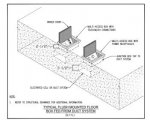
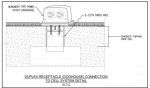
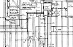
Hoping you guys can see pic. I tried to covert to pdf but itwas too big even after compressing. I have an existing floor cell/trench ductsystem. When installing floor devices as shown in pic I’m assuming you have tocore through concrete then penetrate the top of the cell. How would you dothat, hole saw? Also isn’t it a PIA to pull cables through this system. I’venever come across one of these. Any insight would be greatly appreciated. Thanks,