foolish question about 3 phase

Status
Not open for further replies.
rattus..then if I am connecting a single phase motor to
a 3 phase system by just using two hot legs one of the
legs is leading the other? What effect would this have on
a capacitor start motor?

Ed

Not a thing, because the motor sees only one phase. Same argument for split-phase, shaded pole, cap-start, etc., etc., etc.

Observe this waveform with an oscilloscope. You will see only one signal--one phase. For example, let,

Van = 120V @ 0 (reference)
Vbn = 120V @ -120 (5.6ms later)

Vab = 208V @ 30 (0.93ms earlier)

But, don't connect the ground clip to a hot wire. Use a dual channel scope.

Phase angles can hurt your head. Just remember that the difference in two sinusoidal voltages is always another sinusoid of the same frequency and a different magnitude and phase angle as shown in the above example.
 
Last edited:
Erthimatic Eqvation

Erthimatic Eqvation

transformer plays very significany role in electrical engg.there are mainly two types of transformer.these are single phase and three phase .mainly uses for step up phenomena.as we know that in step up transformer voltage in stepup from low level to high level according to use.we know that in large power requirements generly 3 phase transformer is used in which R,Y,B means red,yellow,black phase sequence is used.
 
transformer plays very significany role in electrical engg... in which R,Y,B means red,yellow,black phase sequence is used.

Welcome to the forum jeckmartin.

I have to wonder what part of the world you hail from. R,Y,B is far from universal. In fact, I've never heard of this color combination associated with a transformer (bank) or any three phase connection.
 
The three phases of a three phase system are separated by 120 degrees of phase angle simply because the generator windings are constructed such that the Phase A windings are separated from the Phase B windings by 120 degrees of physical space (i.e., by a 120 degree angle), and from the Phase C windings by another 120 degrees of angle. I have a prop I use to help me explain electrical theory to some of my colleagues. If I can set aside the time, I will take a photo, and post it here.

The correct term for a circuit that uses two poles from a three phase 120/208 volt system is a "208 volt, single phase circuit." I would like to ask that anyone who has a habit of calling that a "two phase circuit" make an effort to break that habit.
 
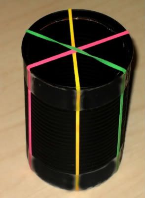
Here is a soup can that I painted black, and to which I attached three colored rubber bands. Let?s use this model to describe a three phase generator.

3-phasemodel-1.jpg


The black can represents the generator?s stator. The notion here is that each rubber band represents a long wire that is wrapped many times around the generator?s stator. Let?s consider the pink rubber band to represent the windings of Phase A, the yellow to represent Phase B, and the green to represent Phase C. You see only one pink rubber band, but consider it to really be one wrapped on top of another, and on top of another, and on top of many others.

You will note that each winding is separated (in physical space) from its neighbor by a 120 degree angle. If you put a magnet inside the can, and spin it counterclockwise (as seen in this photo), then its North pole will first be adjacent to the pink wire, then it will rotate until it is next to the yellow wire, then it will rotate until it is next to the green wire, then it will rotate until it is next to the other half of the pink wire, and so it will continue. That is how the generator is able to give us three signals that are separated from each other by a 120 degree phase angle.

But this photo, this model, has a problem. The three rubber bands meet in the middle of the opening in the can. That is the place that the rotor has to go. So the windings do not actually cross into the middle of that area. Rather, they are wrapped around the edge of the can.

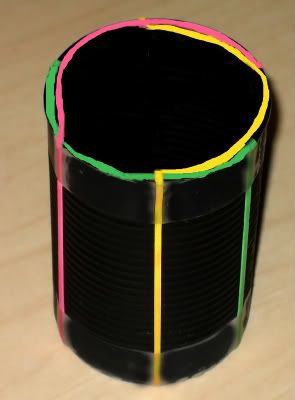
3-phasemodel-2.jpg


In this second photo, I have moved the three rubber bands (using an admittedly crude bit of Photoshop manipulations) such that they appear to go up one side of the can, then around the top edge, and disappear down the opposite edge. It should at least give you a rough idea of how a generator is constructed.
 
Solution to all motor questions in general...


41Z6MS85ZML._SL500_.jpg


I have the 2nd edition, but was well worth the cost.​


For more information, go here.
 
Observe this waveform with an oscilloscope. You will see only one signal--one phase. But, don't connect the ground clip to a hot wire. Use a dual channel scope.
And display Ch1-Ch2....
Or maybe use an isolated battery-powered oscilloscope.
And I agree with your point - line-line is single phase.
 
Charlie, I really like the second picture/Diagram, I understand the phases in rotation.
I think its just hip!
I've never seen it presented that way, Good Show!
 
Cad,
My comments may be taken as a semantic thing.

All three waves are present at the first moment of measurement.
Visualize an oscilloscope, three channel, and select your 'start' point.

The three wave forms always exist together, at any instant you measure them.
They stand at 120 degrees phase shift from one another, at all times.
Which one we call A, B, and C,
may be matter of choice, but the others are always 120 degrees off that phase.

Comments are welcome.
 
Thank you everyone who responded to my questions.
I learned a few things (not a moment too soon) from this.
Regarding my motor question in a conversation today with
a tech he stated a 240 volt motor with a 1.15pf would be fine
at 208 volts.Also as rattus said it would not matter that the system
was either single or three phase.

Ed
 
. . . a tech . . . stated a 240 volt motor with a 1.15pf would be fine at 208 volts.
I have two problems with that statement.

First, if you apply 208 volts to a motor rated at 240 volts, it will draw more current than it would with a 208 volt supply. The question of whether it can handle that extra current can only be answered by its manufacturer. If the manufacturer states that the motor can be run at 208 and at 240, then you are fine. If not, you run the risk of overheating and damaging the motor. The tech may have been right, in saying it would work. But it might not work for long, before it becomes destroyed.

Secondly, I think you meant (or the tech meant, if you accurately quoted his statement) that it has a 1.15 sf (service factor), not a 1.15 pf (power factor). Power factor must absolutely and always be a number not greater than 1.0.
 
....
All three waves are present at the first moment of measurement.
I never said that all power was not there, I made a comparison of A to B to C with all three rotating about a circle. I did say that "A" gets to be first (consider this all in respect to the simpliest of explainations).
Visualize an oscilloscope, three channel, and select your 'start' point.
The three wave forms always exist together, at any instant you measure them.

It's just that I've never seen a diagram as Charlie presented it... : )
I think it's a real cool 3-D graphic...
 
Welcome to the forum jeckmartin.

I have to wonder what part of the world you hail from. R,Y,B is far from universal. In fact, I've never heard of this color combination associated with a transformer (bank) or any three phase connection.

RYB* was used in UK until recently and, of course, many three-phase installations exist wired in those colours. It is not now permitted in UK for new installations. There may be other British influenced countries, ex-commonwealth for example, that still use it.

*RYB is Red, Yellow, and Blue for the three phases with Black for the neutral.
The new colours are Brown, Black, and Grey with Blue now being the neutral.
You can imagine the potential for confusion when it comes to interfacing a new and an existing installation.

There are many here who see this as a monumentally stupid and dangerous move.
 
RYB with Neutral = black.
Wow!
Years back, I had to reverse engineer some Swedish equipment, for maintenance purposes, and it was totally surprising. I recall finding Blue as a neutral.
You would think that the international electrical group would have adopted a standard.

Could it be that this RYB
is an attempt at bringing together several 'other' color codes?

I can imagine that ten European countries might have ten different color codes!
We have 50 states with the same basic color code.

Comments?
 
Cad,
You're OK.

I also think Charlie's graphic is a clear picture of where the fields are,
all at one time.

If the sequence of 'concept' and 'construction' is presented this way,
then the idea pops right out!
 
RYB with Neutral = black.
Wow!
You would think that the international electrical group would have adopted a standard.

Could it be that this RYB
is an attempt at bringing together several 'other' color codes?
Actually, we are moving away from RYB to supposedly "harmonise" with other EU countries.
Interface a new and existing installation and this is what you get:
harmonisedcolours2.jpg


Note that the blue and black wires have a phase-neutral change in designation. It is mad, potentially dangerous and totally pointless.
 
Status
Not open for further replies.
Top