Form Wound Vs Random Wound Coils for Motors

Status
Not open for further replies.

W@ttson

Senior Member
Location
USA
Hello,

NETA ATS makes a differentiation for what the minimum insulation resistance value should be for motors if they have random wound or form wound coils. How can you figure out if the motor has random or form wound coils? I don't believe that information is typically labeled on the nameplate.
 
Hello,

NETA ATS makes a differentiation for what the minimum insulation resistance value should be for motors if they have random wound or form wound coils. How can you figure out if the motor has random or form wound coils? I don't believe that information is typically labeled on the nameplate.
We found some random coils. They failed after about four weeks. We we replaced them with form wound coils. Those have since worked perfectly for ages.
 
We found some random coils. They failed after about four weeks. We we replaced them with form wound coils. Those have since worked perfectly for ages.
Was there anyway to know that the motor had form vs random wound coils without opening up the housing or calling the manufacturer?
 
What are the specs for the motor you are asking about? I very much doubt you will find form wound coils on a machine below 600V or 200Hp.

-Jon
 
What are the specs for the motor you are asking about? I very much doubt you will find form wound coils on a machine below 600V or 200Hp.

-Jon
I would be looking for squirrel cage induction motors operating up to 480V and up to 300HP.
 
You might find formed coils in the largest of the machines you are looking at, but I would not be surprised if they are all random wound.

If you find a manufacturer who makes formed coil machines in the size range you are looking at, please point me to them. I am working with a custom design where we would love to have small formed coils for various reasons.

-Jon
 
There were a few random wound but that was roughly decades ago. Now we always use formed wound. Typically, we use 60kH to about 780kH.
 
Beo, could you please expand on what you are describing? Maybe we are using different terminology.

When I thing of a formed coil machine, I am thinking of coils formed with square or rectangular wire, in definite ordered layers, generally over-wrapped with additional insulation, where the coil is then twisted into a diamond shape with a 'knuckle' and inserted into the stator. The end copper space has a nice pattern of crossing diagonals.

What is the unit kH? Surely not kilohenry :)

Thanks
Jon
 
Beo, could you please expand on what you are describing? Maybe we are using different terminology.

When I thing of a formed coil machine, I am thinking of coils formed with square or rectangular wire, in definite ordered layers, generally over-wrapped with additional insulation, where the coil is then twisted into a diamond shape with a 'knuckle' and inserted into the stator. The end copper space has a nice pattern of crossing diagonals.
Thanks Jon.

It is just that.
A formed coil.
 
I guess I'd just be surprised to find a formed coil on a 480V 60kW machine. I'd expect it only at much higher voltage. So my second question about units. is 60kH a typo for 60kW, or does it somehow indicate a much larger machine?

-Jon
 
I guess I'd just be surprised to find a formed coil on a 480V 60kW machine. I'd expect it only at much higher voltage. So my second question about units. is 60kH a typo for 60kW, or does it somehow indicate a much larger machine?

-Jon
Thanks Jon.
Typically, it would be 40kW upwards to about 760kW. And normally variable speed.
 
Do you guys manufacture these motors, or do you have a manufacturer that you use for these small motors with form wound coils?

Thanks
Jon
 
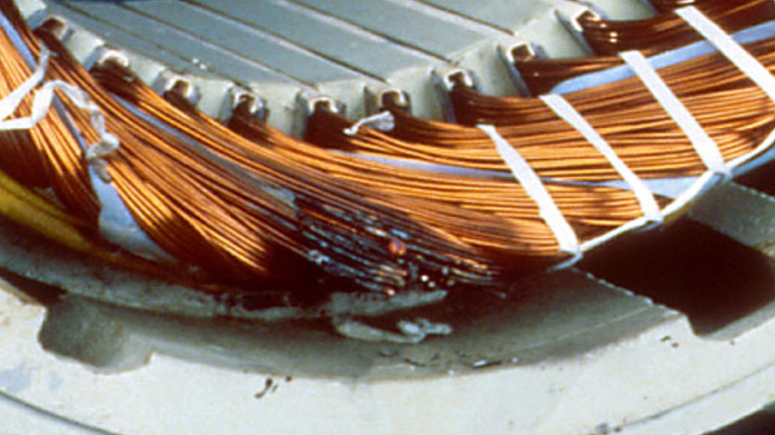
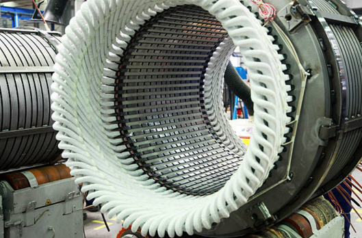
If you can peek into the housing and see the coils, Form Wound would have square or rectangular conductors pressed into precise neat shapes and often vacuum impregnated insulation around them. If you see small round wires wrapped in what looks like sting or tape it's random wound.

Form wound:
Screen-Shot-2017-11-30-at-6.36.25-PM.png


Random wound (with some damage):
motor-failure.jpg


200HP would be a generous lower limit of size to find form wound. It's usually motors that are "above NEMA frame", generally equating to over 250HP at 460V, and even then it's not common until you hit maybe 500HP and up.
 
200HP would be a generous lower limit of size to find form wound. It's usually motors that are "above NEMA frame", generally equating to over 250HP at 460V, and even then it's not common until you hit maybe 500HP and up.
FWTW, my field is almost all PWM.
 
For reference, do you have the case history on that damage? What voltage machine?
That's am image from EASA (Electrical Apparatus Service Assoc) from a website on leading indicators of different types of motor winding damage. I believe that image was for first-turn insulation breakdown, likely due to being operated on a VFD, and likely 460V. I was just using it as an example of random wound motors.

Here is the updated website for that if you are interested. The image I used I think is from an older iteration.
 
Getting back to OP, NETA is the National Electrical Testing Association. The members go around doing testing but they don’t do any repair work so NETA promotes testing for testing sake without a clue what the numbers mean. There are no engineers or manufacturing representatives in their committees. The common motor testing specs are IEEE 43 and EASA.

Right now IEEE 43 and EASA agree that fir anything over 1000 V use 100 megaohms, temperature corrected. But temperature correction doesn’t.always work. Under 5,000 megaohms the PI text works better for those motors BUT regardless of insulation resistance the graph of insulation resistance vs time over 10 minutes is far more useful than the PI number. You can immediately tell if there is a contamination problem particularly moisture as well as clear signs of current leakage on the graph. I’ve heard rumors the next edition of IEEE 43 might recommend graphical only.

Below 1000 V we have to be a little more precise. With wound rotors (synchronous or induction or DC) EASA has found commonly they don’t pass the 5 megaohms cutoff even brand new. So IEEE recommends falling back to 1 megaohm per kilovolt as does EASA. Insulation is thin here and doesn’t need to be thick since it is insulated by air from the rest of the machine. The chart in the IEEE standard does say 1 megaohm per kilovolt PLUS one megaohm and NETA largely copied the chart but the text says differently. Again if there’s a leakage problem you will see it in a graphical plot of insulation resistance. They also say this is acceptable on asphalt and mica insulation systems that were all pre 1970. I have yet to deal with a pre 1970 motor still in operation on the original insulation so that spec can probably be dropped for everyone except museums.

So they sort of threaten you with 5 megaohms for everything else under 1000 V except form wound motors. A few do exist and as stated they are big, at least 250+ HP and definitely on anything 500 HP and over. It is not marked on the name plate. The big difference is that with random wound you put a sheet of insulation in the slot then pack it as tight as possible to get all the turns in there, then run phase paper between coils and tie the ends tightly with shock cord. The last two steps are “optional” but make a huge difference in terms of surge voltage which matters for VFDs. There are air voids that get filled with epoxy or varnish. On larger motors or higher voltages instead of just dipping we use VPI to fill every void with epoxy, not just cover it and let it soak. So there is physically more insulation even if it is random wound thus way. But form wound coils are flat strips that are formed as the name suggests. There is less air space to begin with. In a random wound coil it is random so there is a possibility that the first and last coils lay next to each other so turn to turn voltage can be full voltage in form wound coils turn to the voltage is limited to the system voltage divided by the number of turns. So turn insulation can be thinner and thus ground wall insulation must be thicker as a consequence.

So the upshot is that “acceptable” ground wall insulation is a higher number (100 megaohms) in larger motors. But let’s go the other way. Say a motor is obviously moisture contaminated. If you run it, it will dry itself out but there is a danger of arcing over. How far can you push things? In old (pre 1970) motors pretty much they all leaked current to ground even brand new. It was there but it was harmless and just a consequence of insulation technology of the day. So we know that 1 megaohm per kilovolt plus 1 megaohm is safe for starting purposes. So that’s a useful lower number for safety. But if the question is about the condition of the motor, under 5 megaohms you need to disassemble it with the rare exception of trying to field dry one no matter what it is. But unless it is over 1000 V or 500 HP or larger, use the 5 megaohm metric.

There is a big issue with ONLY using insulation resistance anyways. Normally it’s a quick test. Temperature correction is based on the internal temperature which you don’t know unless the motor is sitting cold for quite a while. And it matters a lot. The 5 megaohm spec is at 40 C or 104 F. The reading at room temperature can be half and in winter 1/4. So s passing raw reading might be 10-40 megaohms depending on temperature. But often you don’t know temperature internally. And on large motors the megaohm reading is just not reliable at all. This is where PI or especially graphical PI is useful.

So a better spec that catches your concern is to use 5 megaohms across the board under 1000 V (rotors excepted) AND PI 2 to 6 with checking the graph for signs of obvious issues like a flat top (leaking) or “noise” (arcing) or stair stepping (severe cracks).

Read iEEE 43. It explains what’s going on far better and it is in agreement with EASA and explains what the dumbed down NETA ATS is trying to say. I like NETA ATS if you just ignore all the starred tests because it is straight forward, not full of as many errors like NFPA 70B, and isn’t wushu washy like IEEE. But in motor matters it’s not useful.

I’m an engineer for a large regional motor shop. We do everything from tiny foreign made servos where you can’t get parts up to several thousand HP at every voltage. We rebuild and build new custom motors, random or form wound. I do the field service work. I’m always running motor tests and I see all the bizarre stuff. I have the benefit of not only lots of experience but I get to see the actual condition of the motor after tear down when I make a call. So the above advice is based on years of experience seeing the results. When it comes to ground leakage 90% of the time an insulation resistance test takes about 10-20 seconds. You start the test. If it fails it shorts out immediately. If not it usually climbs to tens to hundreds of megaohms immediately then continues to slowly climb. At this point it probably passed the 100 megaohm point so you can just terminate the test unless you are documenting it. If however it is marginal or there are other things going on you will get a marginal PI AND a marginal insulation resistance AND a bad graph. It might barely pass one and not the other numerically but the graph confirms what is happening.

Just running one test is useful as a go/no go test. Insulation resistance run at the starter/drive for instance tells you whether or not to move along, nothing to see here, or check further into what is going on. And even if it passes this one test that doesn’t mean it’s a good motor. You can have shorted or open turns and never get a bad insulation resistance reading. This is very common with VFD reflected wave failures. The failure is in the ends of the first couple turns, not down in the slot. Motor shops run a battery of tests including insulation resistance, PI, resistive unbalance, and inductive unbalance or surge as a first pass. Online tests include vibration, power tests, MCA/MCSA, current unbalance, ground current, no load, heat runs, and sometimes load tests. That’s with a top of the line third party inspected (ISO 9000 or EASA) shop, There is no one text that detects all failures. You run a battery of tests looking for specific failures which reduces the odds of having a problem because you are covering more failure types. For instance you can detect open coils and SOME shorts to ground with a multimeter. A Megger gives you most ground wall failures. A milliohm meter indicates some coil shorts as well as opens. Advanced offline testers pick up more coil shorts especially in the first couple turns. Online tests detect rotor bar damage and eccentric issues. Progressively though we are moving from the most common issues to issues that occur maybe 1-2% of the time. And motor shops putting with customer returns under 1% have to test every motor and look for fairly obscure issues in order to minimize returns below 1%.

I know motors are “simple” machines. The complex part is the dozens of failures that can and do occur and the fact that some are difficult to detect when you have just 3 wires to work with. Fortunately you can find the majority of failures, roughly 90%+, with under $1000 in testing equipment and a little knowledge.

I would strongly encourage you to visit a motor shop for a tour. In fact at least 2 or 3. It is far more helpful to see what is going on in person than reading specs and books. You will quickly see what is going on and why. And incidentally see why shops vary in quality, Yes an engineer is telling you that hands on is far more valuable than books and technical information. I am going to be banned from hanging out with other engineers for my blasphemy. Excuse me while I go give myself fifty lashes for my transgressions.
 
If you can peek into the housing and see the coils, Form Wound would have square or rectangular conductors pressed into precise neat shapes and often vacuum impregnated insulation around them. If you see small round wires wrapped in what looks like sting or tape it's random wound.

Form wound:
Screen-Shot-2017-11-30-at-6.36.25-PM.png


Random wound (with some damage):
motor-failure.jpg


200HP would be a generous lower limit of size to find form wound. It's usually motors that are "above NEMA frame", generally equating to over 250HP at 460V, and even then it's not common until you hit maybe 500HP and up.

More helpful to actually see a form wound and random wound coil out of the motor. Or the diagrams showing a cross section. But the best way is to see them up close and see them installed in a winding shop. Oh there I go again. Books are superior! I must not condemn the engineering profession. Only calculus is truth. All others are inferior. Fifty lashes for my blasphemy. I am not worthy, not worthy,

Seriously it never truly made sense to me until I actually saw it in person.

OP, if you really want to do this right do yourself a huge favor. Megger every motor and take temperature before you hook it up. Do the temperature correction. This does two things. First if someone dropped it or it got full of something sitting in the warehouse (happens more often than you think) or sat in the rain, you can catch it before installation. Second you have a baseline so that in the future you can refer back. Insulation resistance over years changes slowly then quickly starts to drop. Say a new motor tests 1400 megaohms. It now measures 350 megaohms. Temperature corrected. This is very far from 100 megaohms but would you say that a fault is developing and it should be disassembled and checked out with such a huge change? It won’t matter if the motor is random wound, form wound, gas insulated, liquid cooled, or anything else. With a baseline you have your own yardstick that is far better than the engineers in IEEE or EASA guessing for your situation. Insulation resistance, temperature corrected, is trendable and actionable.
 
Getting back to OP, NETA is the National Electrical Testing Association. The members go around doing testing but they don’t do any repair work so NETA promotes testing for testing sake without a clue what the numbers mean. There are no engineers or manufacturing representatives in their committees. The common motor testing specs are IEEE 43 and EASA.

Right now IEEE 43 and EASA agree that fir anything over 1000 V use 100 megaohms, temperature corrected. But temperature correction doesn’t.always work. Under 5,000 megaohms the PI text works better for those motors BUT regardless of insulation resistance the graph of insulation resistance vs time over 10 minutes is far more useful than the PI number. You can immediately tell if there is a contamination problem particularly moisture as well as clear signs of current leakage on the graph. I’ve heard rumors the next edition of IEEE 43 might recommend graphical only.

Below 1000 V we have to be a little more precise. With wound rotors (synchronous or induction or DC) EASA has found commonly they don’t pass the 5 megaohms cutoff even brand new. So IEEE recommends falling back to 1 megaohm per kilovolt as does EASA. Insulation is thin here and doesn’t need to be thick since it is insulated by air from the rest of the machine. The chart in the IEEE standard does say 1 megaohm per kilovolt PLUS one megaohm and NETA largely copied the chart but the text says differently. Again if there’s a leakage problem you will see it in a graphical plot of insulation resistance. They also say this is acceptable on asphalt and mica insulation systems that were all pre 1970. I have yet to deal with a pre 1970 motor still in operation on the original insulation so that spec can probably be dropped for everyone except museums.

So they sort of threaten you with 5 megaohms for everything else under 1000 V except form wound motors. A few do exist and as stated they are big, at least 250+ HP and definitely on anything 500 HP and over. It is not marked on the name plate. The big difference is that with random wound you put a sheet of insulation in the slot then pack it as tight as possible to get all the turns in there, then run phase paper between coils and tie the ends tightly with shock cord. The last two steps are “optional” but make a huge difference in terms of surge voltage which matters for VFDs. There are air voids that get filled with epoxy or varnish. On larger motors or higher voltages instead of just dipping we use VPI to fill every void with epoxy, not just cover it and let it soak. So there is physically more insulation even if it is random wound thus way. But form wound coils are flat strips that are formed as the name suggests. There is less air space to begin with. In a random wound coil it is random so there is a possibility that the first and last coils lay next to each other so turn to turn voltage can be full voltage in form wound coils turn to the voltage is limited to the system voltage divided by the number of turns. So turn insulation can be thinner and thus ground wall insulation must be thicker as a consequence.

So the upshot is that “acceptable” ground wall insulation is a higher number (100 megaohms) in larger motors. But let’s go the other way. Say a motor is obviously moisture contaminated. If you run it, it will dry itself out but there is a danger of arcing over. How far can you push things? In old (pre 1970) motors pretty much they all leaked current to ground even brand new. It was there but it was harmless and just a consequence of insulation technology of the day. So we know that 1 megaohm per kilovolt plus 1 megaohm is safe for starting purposes. So that’s a useful lower number for safety. But if the question is about the condition of the motor, under 5 megaohms you need to disassemble it with the rare exception of trying to field dry one no matter what it is. But unless it is over 1000 V or 500 HP or larger, use the 5 megaohm metric.

There is a big issue with ONLY using insulation resistance anyways. Normally it’s a quick test. Temperature correction is based on the internal temperature which you don’t know unless the motor is sitting cold for quite a while. And it matters a lot. The 5 megaohm spec is at 40 C or 104 F. The reading at room temperature can be half and in winter 1/4. So s passing raw reading might be 10-40 megaohms depending on temperature. But often you don’t know temperature internally. And on large motors the megaohm reading is just not reliable at all. This is where PI or especially graphical PI is useful.

So a better spec that catches your concern is to use 5 megaohms across the board under 1000 V (rotors excepted) AND PI 2 to 6 with checking the graph for signs of obvious issues like a flat top (leaking) or “noise” (arcing) or stair stepping (severe cracks).

Read iEEE 43. It explains what’s going on far better and it is in agreement with EASA and explains what the dumbed down NETA ATS is trying to say. I like NETA ATS if you just ignore all the starred tests because it is straight forward, not full of as many errors like NFPA 70B, and isn’t wushu washy like IEEE. But in motor matters it’s not useful.

I’m an engineer for a large regional motor shop. We do everything from tiny foreign made servos where you can’t get parts up to several thousand HP at every voltage. We rebuild and build new custom motors, random or form wound. I do the field service work. I’m always running motor tests and I see all the bizarre stuff. I have the benefit of not only lots of experience but I get to see the actual condition of the motor after tear down when I make a call. So the above advice is based on years of experience seeing the results. When it comes to ground leakage 90% of the time an insulation resistance test takes about 10-20 seconds. You start the test. If it fails it shorts out immediately. If not it usually climbs to tens to hundreds of megaohms immediately then continues to slowly climb. At this point it probably passed the 100 megaohm point so you can just terminate the test unless you are documenting it. If however it is marginal or there are other things going on you will get a marginal PI AND a marginal insulation resistance AND a bad graph. It might barely pass one and not the other numerically but the graph confirms what is happening.

Just running one test is useful as a go/no go test. Insulation resistance run at the starter/drive for instance tells you whether or not to move along, nothing to see here, or check further into what is going on. And even if it passes this one test that doesn’t mean it’s a good motor. You can have shorted or open turns and never get a bad insulation resistance reading. This is very common with VFD reflected wave failures. The failure is in the ends of the first couple turns, not down in the slot. Motor shops run a battery of tests including insulation resistance, PI, resistive unbalance, and inductive unbalance or surge as a first pass. Online tests include vibration, power tests, MCA/MCSA, current unbalance, ground current, no load, heat runs, and sometimes load tests. That’s with a top of the line third party inspected (ISO 9000 or EASA) shop, There is no one text that detects all failures. You run a battery of tests looking for specific failures which reduces the odds of having a problem because you are covering more failure types. For instance you can detect open coils and SOME shorts to ground with a multimeter. A Megger gives you most ground wall failures. A milliohm meter indicates some coil shorts as well as opens. Advanced offline testers pick up more coil shorts especially in the first couple turns. Online tests detect rotor bar damage and eccentric issues. Progressively though we are moving from the most common issues to issues that occur maybe 1-2% of the time. And motor shops putting with customer returns under 1% have to test every motor and look for fairly obscure issues in order to minimize returns below 1%.

I know motors are “simple” machines. The complex part is the dozens of failures that can and do occur and the fact that some are difficult to detect when you have just 3 wires to work with. Fortunately you can find the majority of failures, roughly 90%+, with under $1000 in testing equipment and a little knowledge.

I would strongly encourage you to visit a motor shop for a tour. In fact at least 2 or 3. It is far more helpful to see what is going on in person than reading specs and books. You will quickly see what is going on and why. And incidentally see why shops vary in quality, Yes an engineer is telling you that hands on is far more valuable than books and technical information. I am going to be banned from hanging out with other engineers for my blasphemy. Excuse me while I go give myself fifty lashes for my transgressions.
Wow what a wealth of knowledge. I am familiar with IEEE 43 and EASA AR 100. I like referencing NETA because it has the words "Acceptance" and "Maintenance" in its name and can recommend them easily enough to clients and electrical contractors to follow.

I am going to go back through your post a few times because you touch on a few things that can only be developed with years on hands on intimate experience so I would like to greatly benefit from that.

thanks for the post
 
Status
Not open for further replies.
Top