GEC for 400A service

Status
Not open for further replies.

paul32

Senior Member
Location
Minnesota
I took this picture from another thread (thanks George:) ) since it reflects my question better than that the setup in that thread.

Docs320Ametersocket.jpg


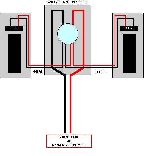
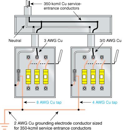
This is a service lateral to the meter socket (outside house), with separate conduits to the 200A panels (in the basement). My question is about connecting the GEC. Can it be connected to the neutral in just one of the panels or does it have to go to both? I couldn't find anything that said one way or the other. Going to both creates a parallel path for neutral current that I don't like, but it seems odd to connect the GEC to only one panel also. The handbook showed only the GEC to a gutter with the neutral before being separated to the two panels. The meter socket would work also, but I know our inspectors would not allow that connection for being not "accessible." Even if connected to just one panel, I assume the size would be 1/0 based on the 600 AL.
 
As long as the neutral to all panels is larger or equal to 1/0 cu or 3/0 aluminum, you can run the GEC from any one panel. Section 250.142(A) allows this -- you can run the GEC from any point on the service neutral and that neutral will bond/ground all the other equipment.

250.64(D) also permits the smaller GEC taps. You'd need to do that if the grounded conductors going to the other disconects was smaller than 250.66 mandates for the whole service (say you had a 100, 200, and 400A panel on a 600 amp service and didn't want to run a huge grounded conductor to the 100A panel)
 
I recall a conversation about this a few months ago. It was called "A discussion between two inspectors" or something like that, and a similar arrangement was described. If memory serves, the consensus was that a full-sized GEC pulled to one of the service disconnects was acceptable, since the two panelboards comprised one service.

I can go looking for the thread, but I'm out of time this morning.
 
400a

400a

In this area we would go to the meter w/ the GEC 250.24 (A) (1), "in some localities this would not be allowed ie. accessible point (which leads to much discussion. Of course two grd rods. then on the inside 250.64 (D)
 
Howdy,

The method IWIRE is speaking about is a optional method that can be used for taps to the GEC but it is not mandatory it be done that way.

The 2008 NEC will clear this up even more as it had redone the section to deal with this exact problem but basically it says you can connect the GE to (3) specific points Meter Can, Service Disconnect Location or Grounded Conductor on the mast ( being brief on those )

In the setup you describe let say you have no water pipe to deal with and you are lets say dealing with 2002 NEC and your electodes are Rod for example then it need not be larger than # 6 AWG regardless.

Because this section is so screwed up basically you can run a single GEC from the meter enclosure to the GE if you wish...size it based on 250.66 or it's exceptions with regards to Ufer and rods and what have you.

The important thing is bonding the second enclosure to the first which gets you past the tapping issues and so on.

What makes the method IWIRE describes as a option....the language in the article itself where it says Shall Be Permitted.....view the admin section of the NEC and that is reference to optional.
 
paul32 said:
I assume the size would be 1/0 based on the 600 AL.

Also what is your GE?...you did not state that so if you are using ground rods no need to be any larger than # 6 AWG CU regardless of the size, If you are dealing with a UFER than no requirement to be larger than # 4 AWG CU.

Otherwise you are correct 1/0AL either way Cu or AL

If you use the option IWire provided your taps would be # 4 CU from each to the unbroken common GEC which would be the 1/0 as stated.
 
I have always wondered why deliberatly creating parallel neutral paths by making loops with multiple GEC's as shown in the handbook graphic is permitted.

IMO, one GEC connection should be made ahead of multiple switches

Roger
 
Roger,
IMO, one GEC connection should be made ahead of multiple switches
But each service disconnect is required to have main bonding jumper and where the service raceways are metallic, this becomes a code required parallel path. Thre are a lot of parallel paths that are required or permitted on the line side of the service disconnect.
This ok because the electrons behave differently on the line side of the disconnect than they do on the load side:grin: .
Don
 
Thanks for the replies.

In the thread George found, generally going to one panel was acceptable.

Bob, in your picture, if you have the gutter with the neutral splice anyway, I would think connecting the GEC there would make the most sense. It would be simpler than making the taps, and then it would not create the parallel connection (water pipes etc aside :smile: ).

But I do have to wonder why the tap thing is there if it is allowed to go to just one panel. Why would anyone want to use a permission to run extra unnecessary wires to get to the other panel?
 
don_resqcapt19 said:
Roger,
This ok because the electrons behave differently on the line side of the disconnect than they do on the load side:grin: .
Don

Don, some how I have to get it in my head that this is in fact the case. :grin:

Roger
 
Last edited:
don_resqcapt19 said:
Roger,

CMP 5 doesn't seem to have any trouble with that concept:grin:
Don

You know, in a strange kind of way, I get the feeling those guys would be fun to hang out with. :grin:

Roger
 
New to the Forum But I have been reading here for a long time. I finally took the time to register. Anyway I have a question on this thread. Looking at the first post diagram, What if the water line entering the building was right next to the service and this was a CT cabinet instead of a meter socket. My question is would it be acceptable to run a #4 from each disconnect to the water pipe? I know it would be just as simple to run a #2 to the bonding bolt on the CT cabinet But my question is just CAN you run a seperate #4 from each disconnect to the water pipe? (yes it is within 5' of entering the building)
 
Chris6245 said:
New to the Forum But I have been reading here for a long time. I finally took the time to register. Anyway I have a question on this thread. Looking at the first post diagram, What if the water line entering the building was right next to the service and this was a CT cabinet instead of a meter socket. My question is would it be acceptable to run a #4 from each disconnect to the water pipe? I know it would be just as simple to run a #2 to the bonding bolt on the CT cabinet But my question is just CAN you run a seperate #4 from each disconnect to the water pipe? (yes it is within 5' of entering the building)

It is a question that has been cleared up by our own Mike Holt in the 2008 revision of the NEC. Up until now it was left as " Could Ya "....and most would say no......has to be the approved methods but the section was so messed up that it took a total re-write to make it clear... in the new language in regards to the 2008 NEC ROC you can indeed run individual GEC's from each disconnect in the example to the GE

Here is the new verbage :

(2) Individual Grounding Electrode Conductors. A
grounding electrode conductor shall be connected between
the grounded conductor in each service equipment disconnecting
means enclosure and the grounding electrode system.
Each grounding electrode conductor shall be sized in
accordance with 250.66 based on the service-entrance conductor(
s) supplying the individual service disconnecting
means. [ROP 5–192]
 
Last edited:
Status
Not open for further replies.
Top