Generator feeding two ATS's

Status
Not open for further replies.
All,

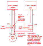
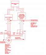
I have a generator which feeds two ATS's.
Each ATS will feed panel loads which are normally fed by two separate transformers from the utility (both 120/240V utility).

I am just trying to figure out if I have a code violation with the way the system is configured. Please note it's an existing system therefore we are just trying to assess the situation. The primary scenario at hand is that the service transformer neutrals may be tied together at some point.
 

Attachments

  • ats_gen_diagram.PNG
    ats_gen_diagram.PNG
    31.7 KB · Views: 25

Dsg319

Senior Member
Location
West Virginia
Occupation
Wv Master “lectrician”
Floating neutral genset or bonded?

In theory I can’t see that being correct if in the case of a lost neutral from one source returning via the other service drop/transformer.

maybe I’m wrong can’t really get my head wrapped around it. Only way I can see is having switched neutral ATS.
 
Last edited:

kwired

Electron manager
Location
NE Nebraska
Floating neutral genset or bonded?

In theory I can’t see that being correct if in the case of a lost neutral from one source returning via the other service drop/transformer.

maybe I’m wrong can’t really get my head wrapped around it. Only way I can see is having switched neutral ATS.
Even without having the generator and transfer switch(es) you will potentially have parallel pathways between the two services, especially if both services are supplying same building/structure as they should both tie to a common grounding electrode system and likely are bonded together at the source(s) as well via the MGN that is common to both primary and secondary at the source. Like it or not this is normal and NEC compliant as is.

What you don't want is to have a grounding connection at the generator neutral as well as at the service disconnect unless you switch that neutral in the transfer switch, that leaves potential parallel path for neutral current to the generator neutral via ECG and/or equipment, raceways, etc. between service and the generator.

OP drawing doesn't show grounding at generator, also says not separately derived on the drawing, but what is missing is there should be an EGC drawn in there both to the supplied load(s) and to the generator frame (with no bond to neutral other than in the service disconnect(s)).
All, my apologies for a non-detailed drawing. I have updated the drawing. xfmr 1 is a small pole mount utility owned, xfmr 2 is customer owned onsite. However there is a big entrance transformer which feeds everything. My only concern is that while both transformers are fed by a big utility service transformer, whether or not it would be acceptable to only switch one of the neutrals and have the other as solid. This could create a scenario where the neutrals are tied together from different transformers however they are fed by the same utility fundamentally.
 

Attachments

  • ats_gen_diagram.PNG
    ats_gen_diagram.PNG
    42.7 KB · Views: 10

kwired

Electron manager
Location
NE Nebraska
All, my apologies for a non-detailed drawing. I have updated the drawing. xfmr 1 is a small pole mount utility owned, xfmr 2 is customer owned onsite. However there is a big entrance transformer which feeds everything. My only concern is that while both transformers are fed by a big utility service transformer, whether or not it would be acceptable to only switch one of the neutrals and have the other as solid. This could create a scenario where the neutrals are tied together from different transformers however they are fed by the same utility fundamentally.
So what is utility and what is customer equipment and where is the service disconnect?

Presumably the customer owned transformer should have a service disconnect in it's supply conductors.

That still shouldn't effect how you would connect a transfer switch to the secondary though, you run an EGC from generator to EGC of that secondary and do not bond it to the any point between system bonding jumper and generator neutral. System bonding jumper is where the current carrying grounded conductor and the EGC separate whether the supply is the utility, SDS created by the transformer or the generator. With that arrangement the EGC never carries any current other than during ground fault conditions.
The utility owns the service + XFMR #1. XFMR #2 is customer owned. The service disconnect is at the large upstream transformer (see drawing above) which feeds everything. The customer transformer has a service disconnect nearby. The generator has a ground rod where an EGC is run to each ATS. Each ATS furthermore has a ground conductor running back to the system ground point to ensure a safe path for fault current. In the drawing, the "ground conductor" on the generator is referring to EGC.
 

kwired

Electron manager
Location
NE Nebraska
The ground rod at the generator is totally optional in a non SDS setup.

Each supply whether service or not all need tied to same grounding electrode system, which makes them all have the same grounding reference and eliminates any possible voltage between non current carrying components of each system.

The EGC to the generator needs to connect to a point that is either at or "beyond" the main bonding jumper and not connect to the neutral at the generator. That extends the EGC to generator frame without introducing any normal operation neutral current to that EGC or the generator frame. Neutral from generator should connect to neutral at each transfer switch. If each transfer switch is service equipment (or first disconnect of the separately derived system and has neutral bonded there) then you do have some potential of stray currents on non current carrying components between the two, but you still have that possibility even without introducing the generator and transfer switches and NEC doesn't call that objectionable current. But that stray current possibility is even less here with the one separately derived system than if both supplies were services because the secondary neutral current of the SDS is trying to get back to that transformer and not to the utility transformer. If it were two "services" all the bonding between the two ahead of the service disconnects would allow for current from either one to flow on components of the other and through upstream bonding points before getting back to the source.
 
I follow everything, I guess my only question is. If you configure the generator as non-sds (i.e. one of the ATS's has a solid neutral tie to the source transformer and there is no bond between the generator neutral and chassis). Would it be safe to switch the neutral on the other ATS?
 

kwired

Electron manager
Location
NE Nebraska
I follow everything, I guess my only question is. If you configure the generator as non-sds (i.e. one of the ATS's has a solid neutral tie to the source transformer and there is no bond between the generator neutral and chassis). Would it be safe to switch the neutral on the other ATS?
I see no reason to do so. You will not isolate anything by doing so. everything is still tied together via EGC and GEC, and also is if you switched both neutrals. Where you need to switch the neutral is if you have bonded the neutral at the generator. This seldom really needs to be done, mostly on 480/277 systems where GFP is required is where you have little choice but to ground ahead of the GFP device or else you will get unintended tripping of the GFP.
 

synchro

Senior Member
Location
Chicago, IL
Occupation
EE
The primary scenario at hand is that the service transformer neutrals may be tied together at some point.
My only concern is that while both transformers are fed by a big utility service transformer, whether or not it would be acceptable to only switch one of the neutrals and have the other as solid. This could create a scenario where the neutrals are tied together from different transformers however they are fed by the same utility fundamentally.
I follow everything, I guess my only question is. If you configure the generator as non-sds (i.e. one of the ATS's has a solid neutral tie to the source transformer and there is no bond between the generator neutral and chassis). Would it be safe to switch the neutral on the other ATS?

ATS1 switches its load neutral between that from Xfmr #1, or that from the generator and Xfmr #2. And so it never connects the neutral of Xfmr #1 to the neutral of the generator and customer Xfmr #2.

If you also switch the neutral on ATS2 2, then you are switching its load neutral between the Xfmr #2 neutral and the generator neutral. That would be OK if you want to make the generator a separately derived system with its neutral bonded to the EGC and having a GES.

I don't see any real issue with the schematic shown as long as all EGC's are connected together.
 
Status
Not open for further replies.
Top