Generator Grounding and NEC 230.6

Status
Not open for further replies.

Shujinko

Senior Member
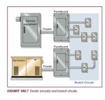
I am designing a project where the client has an existing stand alone building (metal shed) for a stand-by generator that basically backs up the entire campus loop if the utility power goes out. The generator is rated at 480Y/277 and the voltage is stepped up outside of the building to 12470Y/7200V to feed acampus loop. We aren't doing any work on the Medium Voltage side only the Low Voltage Side (480Y/277V) in the metal shed building.

In the building the client is upgrading from (1) 1400KW diesel generator with an ATS to having (3) 500KW diesel generators paralleled with a paralleling switchboard. The neutral and ground will be bonded in the paralleling switchboard and the generator breakers are all in the paralleling switchboard, no breakers at the generators.

If this is the case, would I have to comply with NEC 230.6 and concrete encase the portion of the feeders from the generators to the paralleling switchboard since they will be installed over head (above grade) and system won't be grounded until it reaches the paralleling switchboard?
 

Shujinko

Senior Member
I want to make sure I am not in violation of NEC 230.3...that's why I am thinking I need to comply with NEC 230.6.
 

Shujinko

Senior Member
Sounds like there is no service conductors involved in what you are doing to me, if so then nothing in 230 should apply.

Service Conductors are defined in the NEC as "The conductors from the service point to the service disconnecting means." In my case I am talking about the conductors from the generators to the paralleling switchboard. The "service disconnecting means" are in the paralleling switchboard. Therefore, I think a picky electrical inspector/plans reviewer might pick up on this as being in violation of NEC 230.3 and NEC 230.6. Thoughts?
 

Shujinko

Senior Member
The definition of "Service" relates it to the utility. The generator power is delivered by feeders.

Yes, I think I was getting confused with the definition of a feeder and a service conductor as it relates to a generator. In the NEC a feeder is defined as "All circuit conductors between the service equipment, the source of a separately derived system, or other power supply source and the final branch circuit over current device." As a generator is considered a separately derived system I think the situation I have describes a set of feeders not service conductors. NEC Exhibit 100.7 shows the definition of a feeder as it relates to a generator very well.

On a different note I have to make sure that I am in compliance with all the grounding requirements for a separately derived system in NEC 250.30(A) since my source of a separately derived system and the first OCP/Disconnecting means are at different locations.
 

Attachments

  • feeder.JPG
    feeder.JPG
    38.6 KB · Views: 1

ron

Senior Member
On a different note I have to make sure that I am in compliance with all the grounding requirements for a separately derived system in NEC 250.30(A) since my source of a separately derived system and the first OCP/Disconnecting means are at different locations.

Hopefully the step up transformers you are feeding are Delta - Wye where the delta winding is the 480V side.

That way you can have the N-G bond at the paralleling SWGR and not bring Neutrals to the transformer (only 3W +G) and not have to deal with circulating current issues.
 

Shujinko

Senior Member
Hopefully the step up transformers you are feeding are Delta - Wye where the delta winding is the 480V side.

That way you can have the N-G bond at the paralleling SWGR and not bring Neutrals to the transformer (only 3W +G) and not have to deal with circulating current issues.

We are connecting to an existing step-up XFMR, Y - Y, 480Y/277V primary and 12470Y/7200 secondary. What's your experience with problems with the circulating currents on a step up transformer?
 

ron

Senior Member
We are connecting to an existing step-up XFMR, Y - Y, 480Y/277V primary and 12470Y/7200 secondary. What's your experience with problems with the circulating currents on a step up transformer?
Try to confirm how the existing is connected. Is the existing N-G bonded at the gen and at the step up secondary or not? Is there a Neutral on both the primary and secondary of the transformer brought to / from?
 

GoldDigger

Moderator
Staff member
Location
Placerville, CA, USA
Occupation
Retired PV System Designer
We are connecting to an existing step-up XFMR, Y - Y, 480Y/277V primary and 12470Y/7200 secondary. What's your experience with problems with the circulating currents on a step up transformer?
There are general problems with a transformer with a wye primary and delta secondary, which you often end up with when reversing a standard delta in, wye out transformer.
If you connect the neutral on the wye primary side, any imbalance in primary phase voltages can cause circulating currents in both the delta secondary and the wye primary.
There have been quite a few threads explaining this in detail, so I will not go into it in depth here.

Sent from my XT1585 using Tapatalk
 

kwired

Electron manager
Location
NE Nebraska
Service Conductors are defined in the NEC as "The conductors from the service point to the service disconnecting means." In my case I am talking about the conductors from the generators to the paralleling switchboard. The "service disconnecting means" are in the paralleling switchboard. Therefore, I think a picky electrical inspector/plans reviewer might pick up on this as being in violation of NEC 230.3 and NEC 230.6. Thoughts?
You have indicated that your service is medium voltage - if you are only running 480/277 conductors from the generators you are not dealing with service conductors - therefore nothing in art 230 applies to what you said you are doing.

There is some content in art 225 part II that is similar to some requirements in art 230 though.
 

jim dungar

Moderator
Staff member
Location
Wisconsin
Occupation
PE (Retired) - Power Systems
He said it is a Y-Y

But that is not enough of a description. A Y configuration does not always need to have a neutral point connection (e.g. the windings in a motor).

It is not uncommon to find installations like this step-up transformer where its primary side neutral point is floating (no ground and no neutral).
 

Shujinko

Senior Member
But that is not enough of a description. A Y configuration does not always need to have a neutral point connection (e.g. the windings in a motor).

It is not uncommon to find installations like this step-up transformer where its primary side neutral point is floating (no ground and no neutral).

Here are some pics for reference and analysis.
 

Attachments

  • IMG_7431.jpg
    IMG_7431.jpg
    132.1 KB · Views: 1
  • IMG_7447.jpg
    IMG_7447.jpg
    133.5 KB · Views: 1
  • IMG_7448.jpg
    IMG_7448.jpg
    135.3 KB · Views: 1
  • IMG_7441.jpg
    IMG_7441.jpg
    135.3 KB · Views: 1

jim dungar

Moderator
Staff member
Location
Wisconsin
Occupation
PE (Retired) - Power Systems
Here are some pics for reference and analysis.

You have a GY-GY transformer, it has an internal bonding strap between the HV and LV neutral points, only the X0 has an external connection

I would be looking at the both the MV system as well as the LV side. One project I was on had problems with circulating ground currents when the primary (LV) side neutral was bonded to ground. They had the transformer service group open the tank and break the internal H0-X0 bonding. But, your MV system probably needs to be GY.
 
Status
Not open for further replies.
Top