Generator tripping on ground fault during load test

Status
Not open for further replies.
We have been testing a Cummins VTA-1710-G2 Diesel Generator 1800 RPM 480 Vac 671 kW with an Avtron K580 load bank that is hooked up to our three 480 Vac output cables and one cable to our facility ground. The generator output breaker keeps tripping when the load is around 350 kW. The test requires the load to be maintained at 560 kW for 30 minutes but it keeps tripping when the load bank switches higher than 300-350 kW. The generator output breaker is a TKM3F molded case breaker 1000 amps with a shunt trip coil wired to a Hi-Z model Z-2000 ground fault relay set at 200 amps at 6 cycles delay. Each time the breaker trips we get the ground fault light which indicates the ground fault relay actuated the shunt trip. The Hi-Z ground fault relay gets its signal from a Hi-Z model ZBT rectangular ground fault current sensor. This is a large rectangular laminated core that surrounds the three load output cables, which theoretically would sense an imbalance in the magnetic field if one of the cables had a path to ground, similar to a GFCI theory.

Heres what we know:

The resistors in the load bank and the load cables from the generator all meggered sat. No anomalies and all the resistances in the load bank were balanced 4.4 ohms for each bank. The generator tripped at various combinations of banks to attempt to get over 350 kW so the vendor said it wasn't one specific resistor bank that could be the problem child. Our megger confirmed this.

The generator neutral is ungrounded for reliability reasons since it is an emergency backup application. The generator meggered greater than 4200 megohms to ground. I'm not sure how there is a ground path for current with the generator neutral ungrounded and everything meggering sat as well.

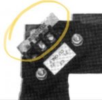
Here's the strangest part I need help figuring out. The ZBT rectangular current sensor has the front side of the rectangle able to be
removed to facilitate load wire installation. When the electricians removed the section of the current sensor to remove the normal load cables and install the vendor load bank cables they did not reinstall the front section of the rectangular sensor and this went unnoticed for a number of attempts at this test. I went out and noticed the front section missing from the CT and could not wrap my head around how this ground fault relay could be getting a signal from a CT with only 3 sides. I thought of an amp clamp that could not be closed around a conductor. Anyway we were grasping at straws and thought the detection circuit could have been acting erratically without a properly installed CT so we put the front piece on the CT and ran the test again and it tripped on ground fault again at the same exact point in the test.

1. How is an ungrounded generator getting a ground circuit and a 200 amp ground fault at that?
2. How does a ground fault relay circuit actuate consistently at the same point in the test with both an incorrectly and correctly installed current sensor?

Any input would be greatly appreciated.
 

gar

Senior Member
Location
Ann Arbor, Michigan
Occupation
EE
181114-1343 EST

knightsof3:

Your initial installation of the current transformer was incorrect. Your magnetic path had a very large air gap. If it is now correctly installed, meaning virtually no air gap, then that is not your problem.

At this point I would put a scope on the CT output and make measurements at various loads. You should see a fairly uniform ripple over 16.7 milliseconds, 1 cycle. The CT output should be approximately a linear increase with load.

You need to know the CT output voltage where GFCI tripping occurs.

Feedback on this information may point in some direction.

.
 

ATSman

ATSman
Location
San Francisco Bay Area
Occupation
Electrical Engineer/ Electrical Testing & Controls
By definition, GF circuit protection is used to protect equipment/ cables on a grounded system. You say the generator winding is not grounded so the GFR system serves no purpose. The GF current sensed to trip the breaker may be due to capacitive coupling of the gen winding to ground. Solid state devices designed for grounded systems can nuisance trip on ungrounded systems. Since your megger readings of the gen and load bank are good, you may try disconnecting the GF system and perform you testing.
 
By definition, GF circuit protection is used to protect equipment/ cables on a grounded system. You say the generator winding is not grounded so the GFR system serves no purpose. The GF current sensed to trip the breaker may be due to capacitive coupling of the gen winding to ground. Solid state devices designed for grounded systems can nuisance trip on ungrounded systems. Since your megger readings of the gen and load bank are good, you may try disconnecting the GF system and perform you testing.

I have no doubts that if we removed the GF relay from the system the test would be successful. Because its tripping on GF only when it gets to 300 - 350 kW anywhere from 300 to 400 amps breaker trips on instantaneous rated at 1000 amps and if it was a true fault the breaker would magnetic short circuit function of the breaker would take it out instantly. This breaker has no thermal overload element just instantaneous 1000 amps. Unfortunately the powers that be would not let me remove the GF circuit because they were afraid of the risk of removing a “protective” function of the equipment. At this point I have to wait for them to reschedule the vendor to bring back the load bank but Im trying to get a game plan ahead of time. I kind of already know its the GF circuit actinf funny either on its own or in conjunction with the vendors load bank circuits so I didnt see too much value in making a huge case in determing the GF circuit and running the test when we already know its the problem.
 

jim dungar

Moderator
Staff member
Location
Wisconsin
Occupation
PE (Retired) - Power Systems
You said you removed existing load conductors and replaced them with the load bank phase conductors. Is the load neutral conductor still in the CT?
 
You said you removed existing load conductors and replaced them with the load bank phase conductors. Is the load neutral conductor still in the CT?
The neutral comes from the generator and connects to a piece of bus bar that is insulated from the rest of the enclosure. The neutral cable does not pass through the CT only the three load conductors.
 

Sierrasparky

Senior Member
Location
USA
Occupation
Electrician ,contractor
The neutral comes from the generator and connects to a piece of bus bar that is insulated from the rest of the enclosure. The neutral cable does not pass through the CT only the three load conductors.

I would think that all the load wires need to pass through the CT any neutral current will cause the unit to trip.
 
The generator neutral is intentionally ungrounded for equipment reliability reasons and the neutral is not used on any circuits it is dead ended and not used and not run thru the CT because it is not used only the three phases are used and there is no reference to ground.
 

Russs57

Senior Member
Location
Miami, Florida, USA
Occupation
Maintenance Engineer
Gee, and I would say leaving it un-grounded is Very Bad for reliability.

I would think high resistance grounding a much better choice.
 

ATSman

ATSman
Location
San Francisco Bay Area
Occupation
Electrical Engineer/ Electrical Testing & Controls
I have no doubts that if we removed the GF relay from the system the test would be successful. Because its tripping on GF only when it gets to 300 - 350 kW anywhere from 300 to 400 amps breaker trips on instantaneous rated at 1000 amps and if it was a true fault the breaker would magnetic short circuit function of the breaker would take it out instantly. This breaker has no thermal overload element just instantaneous 1000 amps. Unfortunately the powers that be would not let me remove the GF circuit because they were afraid of the risk of removing a “protective” function of the equipment. At this point I have to wait for them to reschedule the vendor to bring back the load bank but Im trying to get a game plan ahead of time. I kind of already know its the GF circuit actinf funny either on its own or in conjunction with the vendors load bank circuits so I didnt see too much value in making a huge case in determing the GF circuit and running the test when we already know its the problem.

This is so typical of "higher ups" (corporate lawyers, bean counters, 1st lines, 2nd lines, etc who are so worried of loosing their jobs) making the decisions that I had to dealt with in my whole career. As I stated earlier, the design of your system is invalid....and as you stated, why should you expect valid results?
You don't have an electrical problem..... you have a people problem!
You sound like a young engineer trying to following the rules, I am an older guy and may sound abrupt, but understand what you are going thru.
Play the politics and I hope it all works out.

Just checked your profile......WELCOME TO THE FORUM!!!!!

Thank you. Yes it is frustrating dealing w certain levels of management who don’t understand the common sense end if it. This gf relay is most likely original installation 30 years ago and not designed for an ungrounded neutral wye backup generator. It would provide no equipment oroection to the generator on a ground fault anyway until there was a second fault upstream of the current sensor. This backup generator is ungrounded wye so that a first ground would not trip the generator. Its protected by a 1000 amp molded case breaker for an actual severe overcurrwnt condition and this gf relay protects nothing and just provides nusance trip counteracting the very reliability this is designed for but yet managment thinks this relay is too important to remove during troubleshooting even though they could orovide no drawings or historical documents that show the gf relay is part of the protection coordination
 
After zooming in on the vendor manual image of the CT it appears the 200 ohm 10 watt resistor i saw hanging by one lead is indeed the factory installed burden resistor. This could definitely be the smoking gun, now I just have to wait for them to reschedule the load bank for us to be able to reinstall this resistor.
 

Attachments

  • 8E264A66-C24C-402E-B919-AE4458F8CFB0.jpg
    8E264A66-C24C-402E-B919-AE4458F8CFB0.jpg
    12.4 KB · Views: 1
  • 41CB1D1F-7C12-4A4F-8D4D-56E408419AEE.jpg
    41CB1D1F-7C12-4A4F-8D4D-56E408419AEE.jpg
    11.4 KB · Views: 1
This is so typical of "higher ups" (corporate lawyers, bean counters, 1st lines, 2nd lines, etc who are so worried of loosing their jobs) making the decisions that I had to dealt with in my whole career. As I stated earlier, the design of your system is invalid....and as you stated, why should you expect valid results?
You don't have an electrical problem..... you have a people problem!
You sound like a young engineer trying to following the rules, I am an older guy and may sound abrupt, but understand what you are going thru.
Play the politics and I hope it all works out.

Just checked your profile......WELCOME TO THE FORUM!!!!!
[FONT=&quot]
So we finally got the vendor back with the load bank. We reinstalled the burden resistor across the CT and viola we cranked the generator right up to 570 kW with no issues. Problem solved! Thanks everyone! Now whats gonna eat away at me is the electrical theory aspect of why with no ground fault current and with the CT core both not a fully rectane and also installed correctly fully enclosed, how was a voltage being induced onto the secondary winding of the CT? I guess without the burden resistor the secondary circuit is an open circuit but how was anything at all being induced into secondary circuit to mess with the solid stare ground fault relay? And why was at always when we went over 350 kW, 400+ amps? It consistently tripped at the exact point. My mind would think that if the CT secondary open circuit is screwy it would just trip the unit as soon as a load is applied? Any electrical theory thoughts on why an open circuit CT gets an output at with no magnetic field from the load cables?[/FONT]
 
Status
Not open for further replies.
Top