GFCI recep spitting fire

Status
Not open for further replies.
I don't know all of the nuance of GFCI's but I just couldn't accept what you were saying about the test switch. I quick search of Google turned up this site from Pass and Seymour that disputes your premise. http://tools.passandseymour.com/ProductKnowledge/course.cfm?course_sak=42&cur_page=0&cur_seq=0

Perhaps the older style GFCI's operated the way you describe, but the newer ones automatically open when power is removed. The Fed Govt guidelines for installation tell you to push the button and if the unit doesn't operate it is WIRED wrong. The test button clearly provides an actual fault condition to test the GFCI.

That's the circuit I was looking for. Thanks. As I suspected, the resistor should be visible to a meter when in circuit.

Some testing is in order. And perhaps a dissection.

If there are different types of test operation, that would be good to know.
 
The GFCI test button does not create a fault, it does not use the grounding conductor as a path. This has been the 'listed' way to build a GFCI device since they were introduced in the late 70's.
 
FWIW, I have some spider boxes with, I think, Levaton GFCIs where the test and reset buttons affect the electronics (they're rubber covered and next to the receptacle). One of their "features" is that you have to press reset after applying power to get the contacts to close. Just what I want in a spider box :rant:.
 
Well, I stand corrected..

Brr......

The GFCI in the garage would not test with power off. The one in the bathroom would. They are not the same brand, and I don't know how old the one in the bathroom is, but the one in the garage is only a few months old.

So, some do, some don't. I suppose that's good to know.....
 
The GFCI in the garage would not test with power off. The one in the bathroom would. They are not the same brand, and I don't know how old the one in the bathroom is, but the one in the garage is only a few months old.

Operating the mechanism, to open the contacts, is not a test, it is a manual operation.

There have really only been two major generations of GFCIs, with the dividing line being the requirements from the Consumer Protection Safety Counical, around 2006.
 
It doesn't. Check one for yourself. Shut off the breaker feeding any GFCI and go push the test button. It will trip.

I have had some that may operate when still brand new and never been energized at times - not sure why, maybe something to do with the state it was in when it left production, this has always been on newer units that must be energized before they will reset, but never seen one that has been energized that will trip without power being applied.

That's the circuit I was looking for. Thanks. As I suspected, the resistor should be visible to a meter when in circuit.

Some testing is in order. And perhaps a dissection.

If there are different types of test operation, that would be good to know.
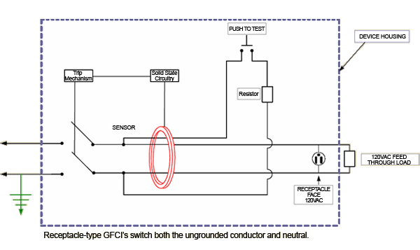
From the previously linked to site:

GFCI2007_5_zpscb50850f.gif


Take a close look at the test circuit in that image.

It draws power from the line side of the CT. One side of the test circuit passes through the CT the other side does not. Pressing the test switch will result in unbalanced current passing through the CT and if it is functioning correctly it will detect this unbalanced current. The test load is determined by the resistor rating and is selected to be near the designed trip setting of the device to ensure that it will trip for a 4-6 mA fault current.

This is why you do not have to have an equipment grounding conductor present to operate the test circuit, yet it still functionally tests for proper operation.

The CT and rest of the trip circuit do not care if there is an equipment grounding conductor or not, they simply respond to voltage that is developed in the CT when there is not balanced current in the circuit being monitored. I would guess that GFCI circuit breakers have a similar test circuit.
 
Operating the mechanism, to open the contacts, is not a test, it is a manual operation.

There have really only been two major generations of GFCIs, with the dividing line being the requirements from the Consumer Protection Safety Counical, around 2006.
But see my link from Pass and Seymour. It shows that the push button does, in fact, injecta fault current in to the device. I remember when the old GFI's were removed from the shelves and the new ones were inserted. I think it is likely that they required the proper testing at that time. After all, it isn't that hard to have the function of the test button be a true test. Just to be clear though, are you asserting that the P and S design in unique, and other manufacturers don't offer the same functionality?
 
But see my link from Pass and Seymour. It shows that the push button does, in fact, injecta fault current in to the device. I remember when the old GFI's were removed from the shelves and the new ones were inserted. I think it is likely that they required the proper testing at that time. After all, it isn't that hard to have the function of the test button be a true test. Just to be clear though, are you asserting that the P and S design in unique, and other manufacturers don't offer the same functionality?

I can't speak for Jim, but I think you misunderstood. I think he was saying that "if the test actually only operated the mechanical features" then it is nothing more than a mechanical test.

I do believe the old GFCI's still performed testing in similar fashion, and was a true test and not just a "mechanical test".

When the changes were made in (around) 2006, they were made to be more "fail safe". You actually have to have power to the device before it will reset. The reset button may physically appear to reset without voltage present, but it will trip again when power is restored. They also added protection from reverse wiring (not reverse polarity, but from supplying load side with power)
 
But see my link from Pass and Seymour. It shows that the push button does, in fact, injecta fault current in to the device.

No, the push-to-test circuit is not not a fault, it is a load connected Line-neutral. All test currents flow on the current carrying conductors, any actual current on the 'ground'has nothing to do with the test of operation of a GFCI.

For the most part, the test portion of GFCIs has not changed since they were first introduced.
I believe, the biggest change occured to the reset mechanism (e.g, can not be reset if device is mis-wired).

And, yes some manufacturers may have mechanically released the contacts at the same time they perform an electronic test.

OK, so I mispoke. The test circuit creates an imbalance between the hot and the grounded conductor. By fault I meant "a defect", which is one of the dictionary definitions of a fault. It was a bad choice of terms for this discussion. I don't even know why you made the point that "any actual current on the 'ground' has nothing to do with the test of operation of a GFCI", since current on the 'ground', I assume you mean the grounding conductor, has nothing to do with the actual operation of the GFCI either.
 
I don't even know why you made the point that "any actual current on the 'ground' has nothing to do with the test of operation of a GFCI", since current on the 'ground', I assume you mean the grounding conductor, has nothing to do with the actual operation of the GFCI either.

I was simply adding, to the discussion, that GFCI's never actually detect 'ground faults'. They simply respond to the imbalance of currents on the normal current carrying conductors of the circuit. Too much current 'coming back on the neutral' (e.g. like could occur on a multi-wire circuit) will cause the device to trip.
 
I was simply adding, to the discussion, that GFCI's never actually detect 'ground faults'. They simply respond to the imbalance of currents on the normal current carrying conductors of the circuit. Too much current 'coming back on the neutral' (e.g. like could occur on a multi-wire circuit) will cause the device to trip.

I thought that might be your point, but I think a lot of electricians wouldn't have been able to interpret that. Just the other day I found it beneficial to explain to a couple of Journeymen how a GFCI actually detects imbalance, because they were trying to troubleshoot a problem and weren't going about it logically. I try not to feel "superior" but I find less, not more typical workers in electrical construction that understand things like how GFCI's work. Then I come here and find out how inferior my understanding is sometimes. (absolutely no sarcasm intended!!!!)
 
It's a good exercise to have your guys take a GFI receptacle apart when you have a broken one to study the mechanisms. It makes a lot of how it functions much easier to understand. I recently had to replace a P&S GFI under warranty which would trip, and was feeding through fine, but didn't have voltage at the GFI itself when reset and the hot wasn't disconnecting to the load. It was a case of the contacts being welded together.
 
Aww I was serious. If they trip with out reason the 2014 kitchen ( refridge) requirements are going to be a real problem.

Sad thing is he was pretty much correct. They supposedly look for particular patterns in the current wave form that could potentially be result of an arcing fault, but sounds like if you go from one Mfgr. to another they do not all look for exactly the same particular patterns.
 
Status
Not open for further replies.
Top